ISO 12354-2017 parts 1-3
Calculation standard ISO 12354
The options described below are available for calculations according to ISO 12354.
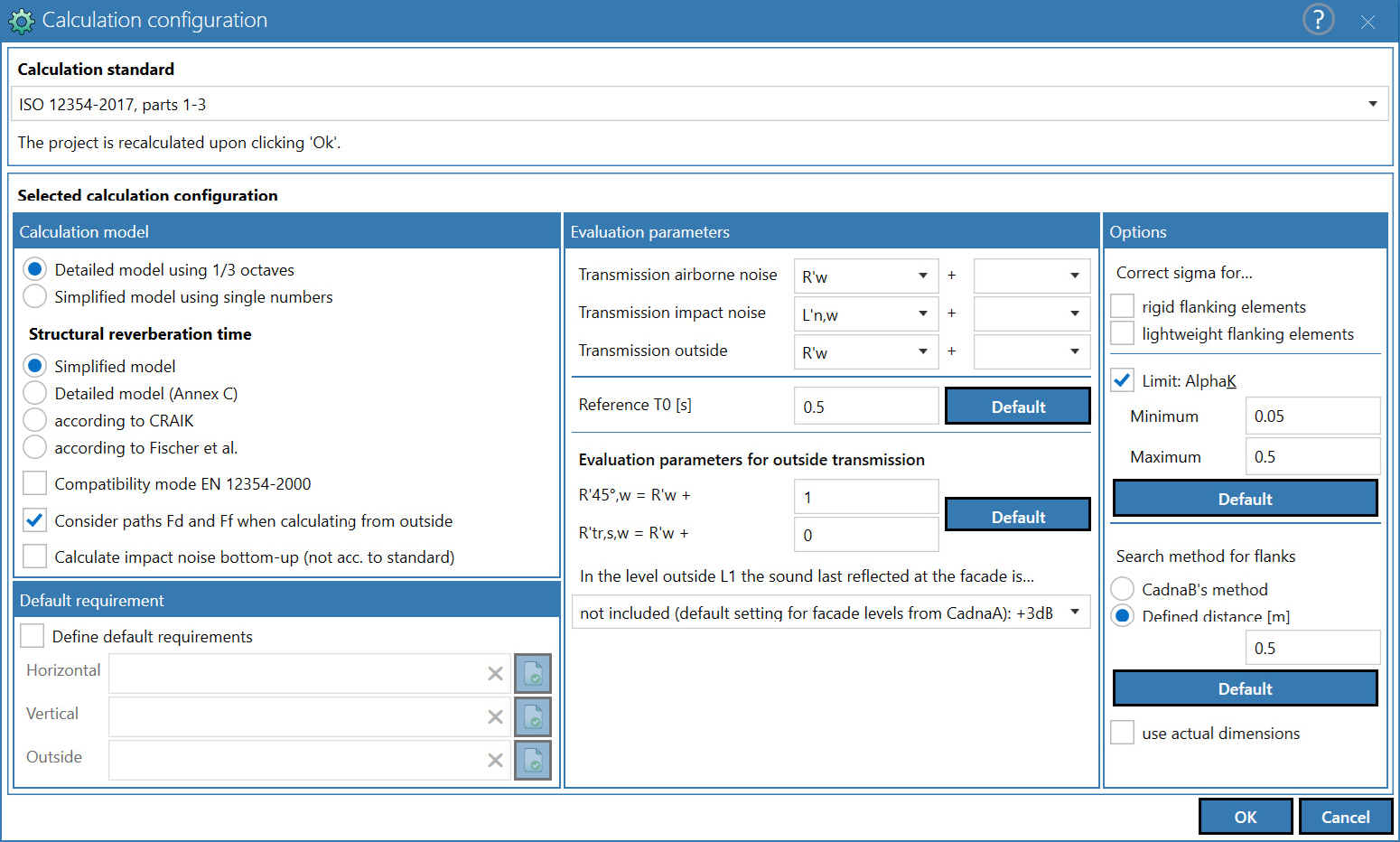
Calculation configuration dialog (for EN 12354)
Dialog options
Calculation model
Calculation models according to ISO 12354 (parts 1-3):
- Detailed model in third-octave bands
- Simplified model with single number ratings
Structural reverberation time, \(R_{situ}\) correction
For heavy single shell rigid components (type A), the sound reduction index is corrected via the structural reverberation time of the component under construction conditions.
The in-situ correction for single leaf rigid components is considered by: $$ \large R_{situ}=R_{lab} - 10 \cdot log\left(\frac{T_{s,situ}}{T_{s,lab}}\right) $$
The consideration of the two-shell design for double-shell rigid components for the determination of \(R_{situ}\) is carried out in accordance with: $$ \large R_{situ}=R_{lab} - 20 \cdot log\left(\frac{T_{s,situ}}{T_{s,lab}}\right) $$
Note
When using the detailed model according to ISO 12354 with a correction for structural reverberation time, the structural reverberation time in the laboratory \(\large T_{s,lab}\) and in the modeled situation (in-situ) \(\large T_{s,situ}\) can be output via the calculation protocol.
If the detailed model is selected, one of the following options can be selected:
- Simplified model: The parameters for identifying the sound insulation of components are viewed as situation-invariant. For joints, the equivalent absorption lengths are calculated based on the areas of the components coupled at the respective joint.
Calculation of the structural reverberation time \(T_{s,situ}\)
Various methods are available for calculating the structural reverberation time in-situ (in the building) if "Detailed model using 1/3 octaves" has been selected under Calculation. For calculations of sound transmission from outside to inside according to DIN EN 12354-3 and for calculations according to the simplified model using single numbers, there is no correction of the structural reverberation time.
- Detailed model according to EN 12354-1, Appendix C:
When calculating the sound transmission, the in-situ correction of the structural reverberation time is calculated directly and depending on the coupling condition for each rigid structure (type A elements) in the model. It is automatically used a calculation when activated in the calculation configuration. The coupling conditions considered at all four component edges result from the current number and position of the rigid components.
Calculation of structural reverberation time for type A elements: $$ \large T_{s,situ} = \frac{2.2}{f \cdot \eta_{tot,situ}} $$
with the total loss factor (tot) considering of the internal loss factor (int), the loss factor for radiation (rad) and the loss factor due to absorption of bending wave energy at the perimeter (rand). $$ \large \eta_{tot,situ} = \eta_{int} + \eta_{rad} + \eta_{rand} $$
The loss factor for radiation is given by: $$ \large \eta_{rad} = \frac{2 \cdot \rho_0 \cdot c_0 \cdot \sigma}{2 \cdot \pi \cdot f \cdot m'} $$
The method according to Timmel is used to determine the radiation factor Sigma.
The loss factor for bending waves at the perimeter of the structure is given by: $$ \large \eta_{rand} = \frac{c_0}{\pi^2 \cdot S \cdot \sqrt{f \cdot f_c}}\cdot \sum_{k=1}^{4} l_k \cdot \alpha_k $$
When determining the absorption coefficients for bending waves alpha at the edges k, only frictionally connected rigid components are taken into account.
| No. | Illustration | Method for $\large K_{ij}$ determination |
| 1 |  |
rigid cross junction |
| 2 |  |
rigid T-junction |
| 3 |  |
rigid T-junction, receiving room shifted |
| 4 |  |
rigid T-junction, sending room shifted |
| 5 |  |
corner, rigid (path Df only, receiving room) |
| 6 |  |
corner, rigid (path Df only, sending room) |
| 7 |  |
Thickness change [Deviation: $K_{Ff} =5 \cdot M^2$; -5 is neglected] |
| 8 | No frictional connection | No frictional connection |
Note
For structural reverberation time for the laboratory case Ts,lab, the total loss factor is calculated via the methods ISO 12354-1 Annex C1 and C3. The following data are taken for the flanks of the test stand: 4 x T-junction; m'\(=\)960 kg/m²; \(f_c=\)46 Hz; room size L\(=\)4 m, W\(=\)5 m, H\(=\)3 m, horizontal transmission LxH, vertical transmission LxB.
Note
User defined vibration reduction indexes \(\large K_{ij}\) are neglected in the calculation.
Note
For rigid components involved in junctions with an entered normalized flanking level difference \(\ \large D_{nf}\), the base component is taken into account with the entered characteristic data. Flanks whose transmission is defined with $\ \large D_{nf}\ $ do not receive a situ correction (junction type no. 16). According to CRAIK: The calculation of the structural reverberation time Ts,situ for rigid components is performed according to CRAIK:
$$
\large T_{s,situ} = \frac{2.2}{f \cdot \eta_{tot,situ}}
$$
with
$$
\large \eta_{tot,situ} = 0.015 + \frac{1}{\sqrt{f}}
$$
Craik, Robert J.M.: Sound Transmission through Buildings using Statistical Energy Analysis, Gower Publishing Ltd, Aldershot, England (UK) 1996.
- According to FISCHER et al.: The calculation of the structural reverberation time \(\ \large T_{s,situ}\) for rigid components is performed according to FISCHER et al: $$ \large T_{s,situ} = \frac{2.2}{f \cdot \eta_{tot,situ}} $$ with $$ \large \eta_{tot,situ} = 10^{0.1 \cdot \left[-12.4 - 3.3 \cdot log \left(\frac{f}{100}\right)\right]} $$ Fischer, H.M.; Schneider, M.; Blessing, S.: Einheitliches Konzept zur Berücksichtigung des Verlustfaktors bei Messung und Berechnung der Schalldämmung massiver Wände, Fortschritte der Akustik (DAGA 2001), Hamburg, Hrsg.: Deutsche Gesellschaft für Akustik DEGA e.V. 2001
Impact noise from bottom to top
By default this calculation is not turned on automatically thus the user will have to set the checkbox “calculate impact noise from bottom to top” in the calculation configuration dialog for the results to be visible in CadnaB. When using the procedure, the message "Calculation configuration not strictly according to standard!" is displayed in the results dialog.
This method is a conservative estimate for the bottom-up impact noise transmission proposed as a first order approximation for this problem not handled in ISO 12354.
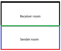
Why this is the case we first take a step back and recapitulate how the vertical impact noise calculation from top to bottom is done according to ISO 12354-2. The calculated result consists of two parts:
-
The direct part – path Dd – is calculated by considering the room’s floor (green), the floor’s screed and the suspended ceiling in the room below, if any.
-
The flanking part – path Df – considers the floor and its screed, all walls in the room below as well as the junctions between the floor and the walls.
If we now invert this situation and want to simulate the result of a tapping machine in the lower room standing on the red floor to the room above we recognize that this is in fact a second order calculation over two sets of junctions. First the floor of the sender room (red) is reverberating which is connected to the walls in the same room. This is the first junction but since we want to estimate the noise in the upper room we have to cross a second set of junctions, namely the ones connecting the upper parts of the sender room with the floor (green) and walls of the receiving room.
The following first step solution was the result of a straight model simplification. The idea is to “block” the effect of the direct part (Dd) since it consists of mainly airborne sound and only consider the flanking paths Df. In the existing top-down case this can be done by adding an artificially high insulating suspended ceiling in the lower room. To account for the second order junction (between the walls and the green floor) one can try to set up an artificial ΔKij but after applying real world measurements it can be concluded that this value can in fact be set to 0dB, thus ignored entirely.
Summary
Impact noise from the slab in the Sender room (marked by a red line) to the Receiver room (above the green line) is conservatively estimated by simply summing up the flanking paths in the Sender room (the walls marked by blue lines) and ignoring the second junction between the walls and the Receiver room slab. This means the effect of various types of slab and floorings in the Sender room may be considered.
Requirement
After activating the "Define default requirements" option, select requirements via  as defined in the Requirement browser (see Requirements Browser) for horizontal, vertical and/or outside transmission. To delete a selected requirement click the
  symbol. Note that the requirement parameters (for airborne and impact sound) must match with the evaluation parameters selected in this Calculation configuration dialog. In case of conflict this will be indicated in the calculation results (see „Results“ Mode).
In the „Results“ mode, a message appears in the corresponding result line if the requirements set are not respected (see „Results“ Mode).
Evaluation parameters
All single number ratings including the spectrum adaptation terms according to EN ISO 717-1 and -2, as well as - if the detailed model is selected - those according to ASTM (E 413-87, E 989-89, E 1332-90) are available.
Airborne sound transmission in buildings
The following ISO evaluation parameters can be selected:
- the weighted apparent sound reduction index R'w
- the weighted normalized level difference Dn,w
- the weighted standardized level difference DnT,w
The combinations of these evaluation parameters with the spectrum adaptation terms C|C100-5000|C50-5000|C50-3150 and Ctr|Ctr,100-5000| Ctr,50-5000|Ctr,50-3150 are calculated automatically and displayed in the Results mode (see „Results“ Mode).
In addition, the following ASTM evaluation parameters can be selected, provided the detailed model is selected:
- the Apparent Sound Transmission Class app. STC
- the Apparent Outdoor-Indoor Transmission Class app. OITC.
Interior Level with Airborne sound transmission in buildings
Provided a permitted evaluation parameter has been selected (i.e. Dn,w or DnT,w, also in combination with a spectrum adaptation term) the interior level can be calculated after selecting a sound source. An interior source is selected via the Constructions mode (see „Constructions“ Mode).
Impact sound transmission in buildings
The following ISO evaluation parameters can be selected:
- the weighted normalized impact sound pressure level L'n,w
- the weighted standardized impact sound pressure level L'nT,w
The combinations of these evaluation parameters with the spectrum adaptation values Ci|Ci,50-2500 are calculated automatically and displayed in the Results mode (see „Results“ Mode).
In addition, the "Apparent Impact Insulation Class" IIC according to ASTM can be selected if the detailed calculation model is set.
Airborne sound transmission outside-inside
The following evaluation parameters can be selected:
- the weighted apparent sound reduction index R'45°,w
- the weighted apparent sound reduction index R'tr,s,w
- the weighted standardized sound level difference D2m,nT,w
- the weighted normalized sound level difference D2m,n,w
The combinations of these evaluation parameters with the spectrum adaptation terms C|C100-5000|C50-5000|C50-3150 and Ctr|Ctr,100-5000| Ctr,50-5000|Ctr,50-3150 are calculated automatically and displayed in the Results mode (see „Results“ Mode).
In addition, the following ASTM evaluation parameters can be selected, provided the detailed model is selected:
- the "Apparent Sound Transmission Class" app. STC
- the "Apparent Outdoor-Indoor Transmission Class" app. OITC.
Interior Level with Airborne sound transmission outside-inside
Provided a permitted evaluation parameter has been selected (i.e. D2m,nT,w or D2m,n,w, also in combination with a spectrum adaptation term) the interior level can be calculated after selecting a sound source. An exterior source is selected via the Constructions mode (see „Constructions“ Mode).
Reference reverberation time T0
The reference reverberation time T0 can be edited for evaluation parameters using the reverberation time (DnT,w, LnT,w, D2m,nT,w). By clicking on the “Standard” button, a reference reverberation time of T0=0.5 s is set (see EN ISO 717).
Evaluation parameters for outdoor noise
When calculating the airborne sound transmission for outdoor noise, the following relationships between the apparent sound reduction index R' and the apparent sound reduction index R'45 ° and R'tr,s or the corresponding single number ratings in the simplified model is used in accordance with EN 12354-3:
\(\large R'_{45°}(R'_{45°,w}) = R'(R'_w) + 1.0\ dB\)
\(\large R'_{tr,s}(R'_{tr,s,w}) = R'(R'_w)\)
To change the preset relation, enter a corresponding value in the input boxes. After a change, clicking the "Default" button resets to the preset values.
Definition Level outside \(L_1\)
This setting specifies whether the reflections existing at the own façade are included in the outdoor level L1 or not. Following options are available:
In the level outside L1, the sound last reflected at the façade is
- not included (default setting for calculated façade levels with CadnaA, default for new projects)
\(C = 3\ dB\) - included, energetically (e.g. measured \(L_{1,2m}\) or calculated with all reflections, default when opening files saved with version 2021 or when importing BASTIAN files)
\(C = 0\ dB\) - included, coherent (e.g. measured \(L_{1,s}\) with microphone attached flush with the surface)
\(C = -3\ dB\)
In all cases diffuse incidence is assumed.
Options
Correct Sigma for ...
- rigid flanking elements
- lightweight elements
These options enable the input data of elements to be corrected with regard to the excitation of free bending waves. All transmission paths except the direct path Dd are affected by this correction.
Limit Alpha_k
The values for the absorption coefficient for bending waves Alpha_k at the borders of a rigid heavy element can be limited when calculating the structural reverberation time. In EN 12354-1, Annex C, a range of 0.05<=Alpha_k<=0.5 is specified. These default values can be set by clicking on the "Default" button.
Search method for vertical flanks
The following methods are available to automatically detect junctions with small offsets:
- CadnaB method: If walls are detected above or below the separating floor slab - starting from the center of the wall - reaching up to half the wall‘s thickness and in one of the two directions - a T or cross junction is assigned. As a result, all vertical junctions extending by a larger distance get a rotated T junction assigned.
- User-defined distance (m): If the central axes of the vertical flanking elements have a horizontal offset (i.e. offset between the storeys) of more than the specified value, a rotated T junction is assigned, but not a T or cross junction. The default setting is 0.5 m. The search method can be set to a distance between 0.01 m and 0.5 m.
use actual dimensions
By default, CadnaB uses the centerline dimensions of walls for geometric calculations. When the “use actual dimensions” option is enabled, wall thicknesses as well as modeled linings are included in the geometry determination. In this case, the wall polygons are intersected within the model to represent the true outer edges of the elements.
This setting has no effect on the room or storey clearance.
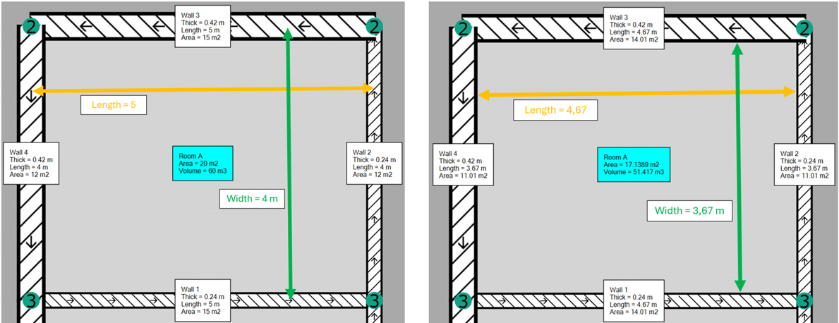
Left: Geometry based on centerline dimensions (option disabled); Right: Geometry with "use actual dimensions" option enabled.