CadnaB Main Window
Starting CadnaB

To start CadnaB double-click on the program symbol on the Windows desktop or select from the start menu of Microsoft Windows the item Programs|DataKustik|CadnaB. Consequently CadnaB is launched and the main window displayed on screen.
Main Window
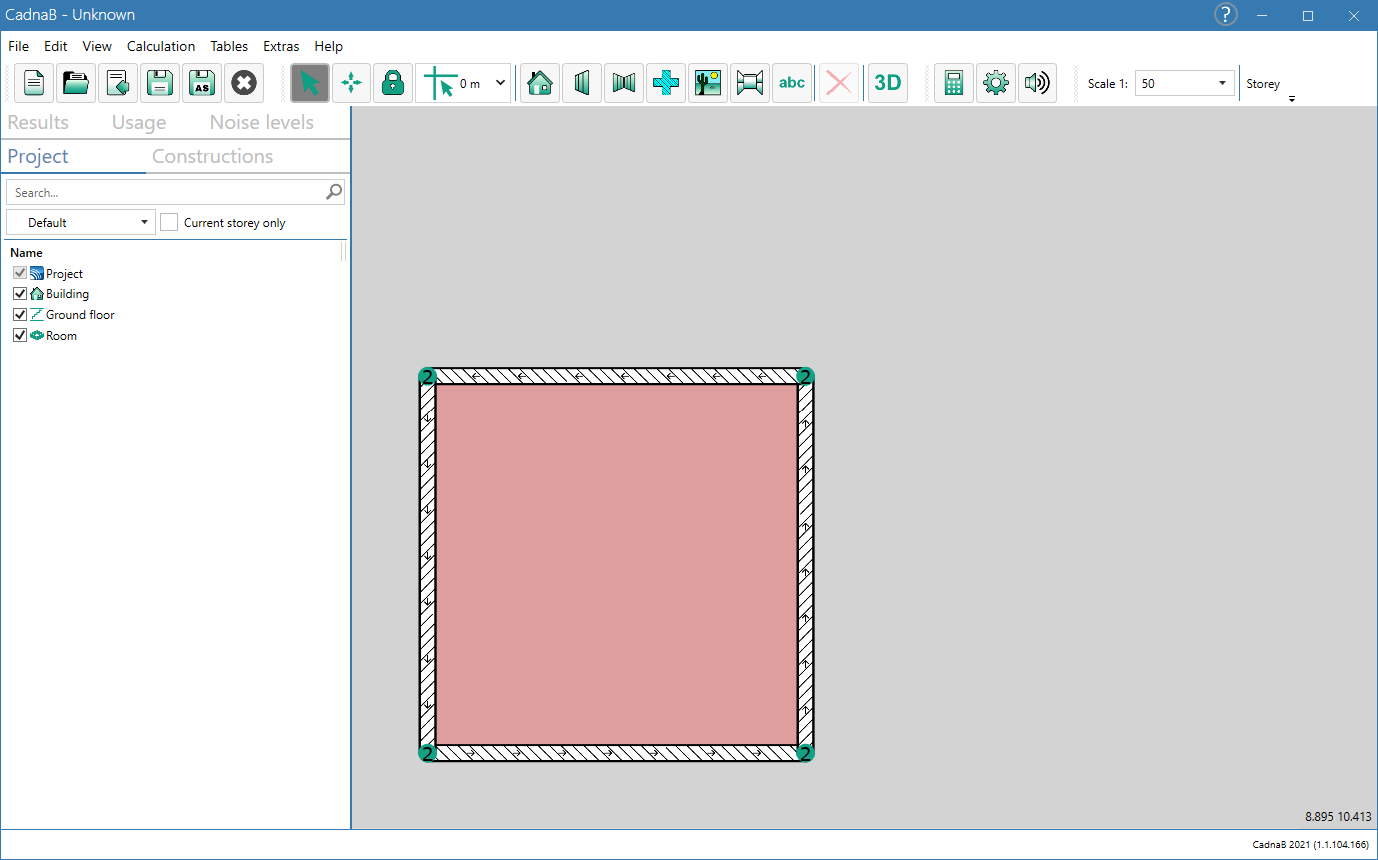 CadnaB main window, display mode "Project“, left: object list, right: area for graphical input
Desktop
The gray area in the right part of the screen is used to enter the components on the currently selected storey (list box “Storey” on the toolbar, standard selection: Ground floor). In the standard setting, a room with 4 walls, floor and ceiling with a floor area of 5x5 m = 25 m² is created.
The coordinates of the current mouse position are displayed in the lower right corner of the workspace.
Menu Bar
The menu bar is used to select commands (see New).
Symbol Bar
When clicking on an icon on the toolbar (see Symbol Bar), the corresponding function is triggered immediately. The function of the symbols is displayed in a "tooltip".
Objects
The list in the left part of the main window depends on the selected display mode (see Edit & Display Modes) and shows all objects in the project depending on the selected display type. The width of the table as well as the width of each column can be modified with the mouse.
Note
For more detailed information on each display mode and their respective specific functions and commands, see Edit & Display Modes. The following text only describes the basics.
The following display modes are available:
- Project (see „Project“ Mode): In this mode, all objects of all object types (project, building, storey, room, floor, wall, junction, window / door, label, etc.) of the current project are displayed. This mode is mainly used for entering new objects or editing existing objects. The display order of the objects is determined internally in the program.
- Constructions (see „Constructions“ Mode): All selected or existing constructions are displayed in the construction list. A red field in the "Construction" column indicates that no construction has been selected for this component.The other columns contain the component thickness d (mm) and the assignment of the component to a floor (column “is contained in”).
- Results (see „Results“ Mode): The "Results" mode shows the calculation results after calculation. The calculation standard is displayed in the header of the list ("Standard" field). Below the results are displayed using the format "SR → RR Xw Yw". Here SR represents the sending room and RR the receiving room, Xw is the evaluation parameter set in the configuration for airborne sound transmission and Yw that for impact sound transmission.
- Usages (see „Usages“ Mode): In the “Usages” mode, a type of usage can be selected for each existing room. Depending on the selected standard, this input is used only for information or to determine whether a requirement has been met or exceeded.
- Noise levels (see „Noise levels“ Mode): The „Noise levels“ mode is used to define indoor levels present in a room or outdoor levels on individual façade elements.
In the status bar on the bottom left, messages are displayed after certain actions (e.g. when saving or after updating an interop calculation). On the bottom right the CadnaB version is always displayed.
Status Line
The CadnaB version is displayed in the status line at the bottom right.