Results Dialog (ISO 12354)
The dialog shows the details of the results for calculations according to ISO 12354 for the transmission situation selected in the "Results" mode (see „Results“ Mode).
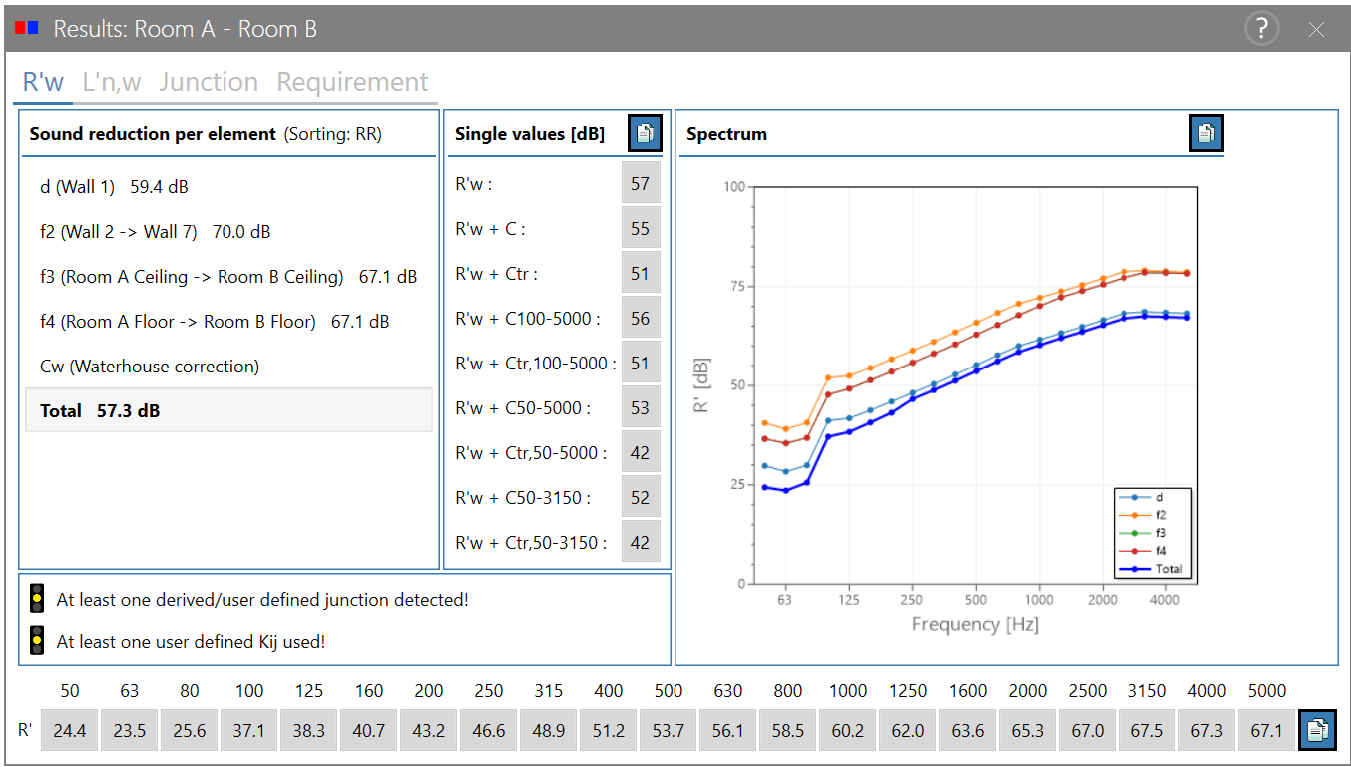
Dialog options
Toggling results
Toggle the results for airborne/impact sound transmission by clicking on the evaluation parameter‘s name (for example: toggling R‘w and L‘n,w).
"Sound reduction per element" list
The list shows the sound reduction index or the impact sound pressure level for each element depending on the sorting type of the flanking paths for the separating element d and the flank elements f1...fn (n = number of flanks) and the total sound reduction index or the impact sound pressure level for the evaluation parameter selected as set in the configuration (see Configuration of calculation).
The paths are sorted by default according to the receiving room side, but can be set (menu Calculation|Sorting, see Sorting).
"Single values (dB)"list
In the case of spectral calculations, this list shows all single number ratings that can be calculated based on the set evaluation parameter (see Configuration of calculation) with and without spectrum adaptation term.
Using the copy button  , the entire list can be copied as text to the clipboard and pasted into other applications.
Diagram options
The frequency diagram shows the spectral evaluation parameters for airborne sound transmission or impact sound per component for each element for the selected sorting and the total sound insulation. For evaluation parameters that are used as a single number value, the sound reduction index or the normalized impact sound pressure level is displayed in the diagram as a substitute.
Using the copy button , the diagram can be copied as a graphic to the clipboard and pasted into other applications.
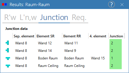
"Junction" tab
The tab “Junction” shows all relevant components on the sending and receiving side for first-order transmissions and the junction type automatically identified by CadnaB for the current room pair.
The first column of the table shows the corresponding icon for the most common junction types. If the mouse is moved over the icon, the display is enlarged.
The color of the table cell in the "Junction" column corresponds to the traffic light in the "Result" mode (see section Traffic light).
"Requirement" tab
The tab "Requirement" shows the current existing or non-existing requirement for this room pair.
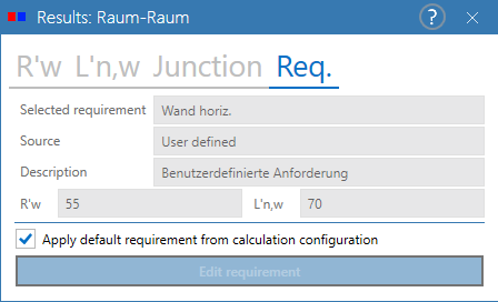
In ISO 12354, the requirement can be defined for all room pairs as a default setting in the Calculation | Configuration menu (see Configuration of calculation) or for a specific room pair after deactivating the checkbox (see screenshot above). The values are compared with the evaluated calculation results in order to check their fulfillment. Consequently, the numerical value used for comparison remains unchanged, even and especially if the target value has been changed. For more information on defining a requirement, see Requirements Browser.
Safety margin
The consideration of a safety margin is left to the user. The safety margin can either be included in the component definition or the requirement value itself can be adjusted.
„Interior level“ option
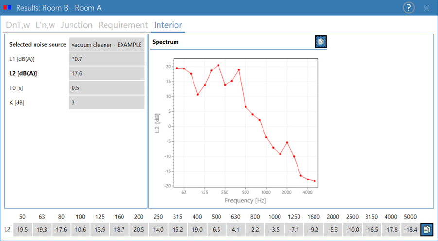
Provided that a permissible evaluation parameter for the indoor level calculation is set (see ISO 12354-2017 parts 1-3), the "Interior" tab displays for each room pair:
- selected sound source
- reference reverberation time T0
- sending level L1 in dB(A)
- receiving level L2 in dB(A)
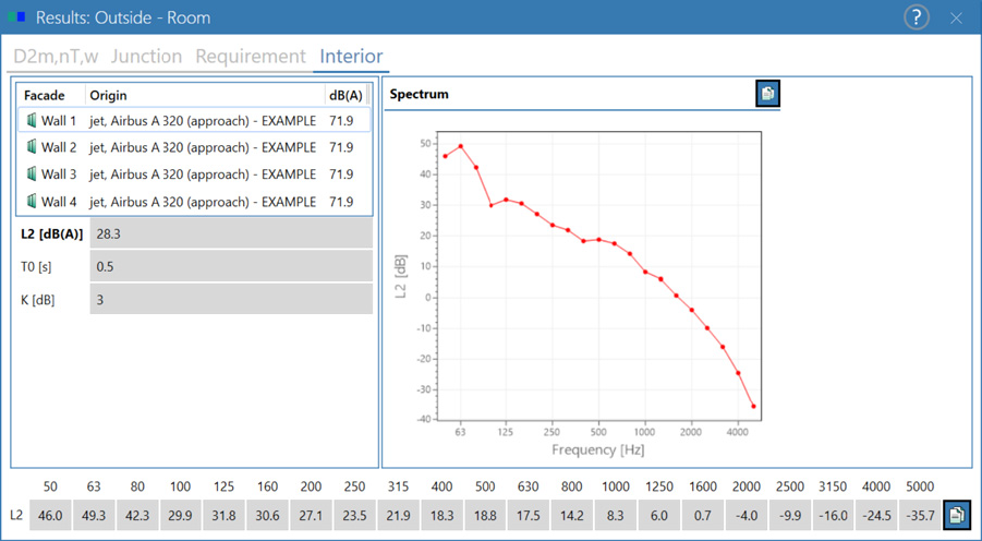
For calculations "exterior → interior", the individual façade components are listed with the respective contribution:
Issues displayed in the results dialog
The messages displayed in the results dialogs with traffic lights for deviations from a calculation performed strictly according to the standard are explained in more detail in Consistency Check.