Wall
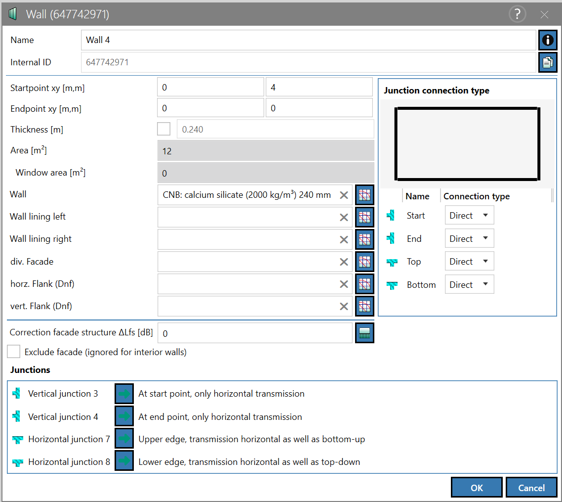
Dialog options
- Name, Memo-field
 , Internal ID: see Common Input Data
 - Start/End point of the geometry (m): The point coordinates refer to the xy-plane. The x-coordinate counts positively to the right, the y-coordinate counts positively upwards.
- Thickness: total thickness d (mm) of the selected construction (from the database dataset). By activating the option, a user-defined width can be entered for display and calculation.
- Area, gross (m²)/Windows area (total window areas (m²)
Selecting a wall construction
wall/additional layer left/right (when looking from first to last point): In order to select or change the wall construction or additional layer, click on the respective selection field  .
.
Selection rules
When selecting element types and constructions, the user must ensure compliance with the following rules:
- single-leaf heavy walls (as interior walls): For this element type one- or two-sided additional layers can be selected.
- heavy double walls: No additional layers can be selected for this element type.
- lightweight double walls: No additional layers can be selected for this element type.
- single-leaf heavy walls (as exterior walls): Only an interior additional layers can be selected for this element type.
Note
It is not possible to select heavy double walls as exterior walls.
Consistency check
Compliance with the above rules is checked by CadnaB as part of the consistency check. If there are any violations, these will be listed in a separate dialog, see Consistency Check.
Appearance additional layer
After additional layers have been selected, this is indicated in the room view by an orange marking alongside of the corresponding element side:
-
one-sided additional layer:

-
double-sided additional layers:

Option „diverging Façade“
This input box is empty by default. In this case, the construction selected in the "Wall“ box is used even if the current wall represents an external wall (façade).
A façade construction differing from the construction selected in the "Wall" field can be selected via the selection symbol . In this case, for the current wall representing an exterior wall (façade), further element types are available which are unsuitable or not permissible for interior walls (e.g. constructions of element types "monolithic wall with ventilated cladding" or "monolithic wall with ETICS") .
Note
Note that the different façade construction is only used when calculating the sound transmission outside>inside. On the other hand, the construction selected in the "Wall" field is used for all transmission paths between rooms inside the building.
Note
Please consider the following additional note: If an exterior wall fulfills the status of an interior wall after selecting a different façade construction, for example by entering new walls, the construction from the "Wall" line is used and the selection „diverging Façade“ is ignored.
Options „horizontal Flank (Dnf)“ and „vertical Flank (Dnf)“
This input box is empty by default. In this case, the construction selected in the "Wall" box is used to calculate the flanking transmission for all paths ij (vertically & horizontally).
A different wall construction can be selected via the selection symbol , describing the flanking transmission via parameter by Dn,f or Dn,f,w (representing just the flanking path ij=Ff). This construction selection applies only to the current room and in particular does not simultaneously select the second flanking element in the neighboring room, the flanking transmission of which is also described by Dn,f or Dn,f,w. To achieve this, the same construction must be selected for the neighboring room (horizontally or vertically) by using the option "horizontal Flank (Dnf)" or „vertical Flank (Dnf)“.
Note
Note that two Dn,f|Dn,f,w can be selected for each wall. One for horizontal transmission and one for vertical transmission. In real cases, situations may arise where up to four different Dn,f|Dn,f,w are required. The restriction may require separate modeling for such a situation or workaround using user-defined vibration reduction indexes in special cases.
Note
If a valid flanking construction (described by Dn,f|Dn,f,w) is selected for the same flanking element of two neighboring rooms, their flanking sound reduction index RFf|RFf,w (in both transmission directions) is calculated based on Dn,f|Dn,f,w. If this flanking wall - at the same time - represents a partition to a room or rooms, the construction data selected under "Wall" is used for the associated flanking paths ij.
Note
If a Dnf is assigned to only one flank component of a transmission path or if two different Dnf are assigned, a consistency check is triggered. By confirming with "OK", the calculation is executed and the Dnf is taken into account at the junction. The input of the sending room is used for the calculation.
Dialog part "Junction connection type"
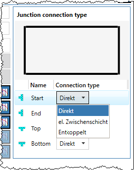
For each element edge (start, end, top, bottom), the type of connection can be selected:
- direct: direct coupling (default selection, element edge black)
- elastic interlayer to the adjacent element (element edge gray): In this case, the flanking transmission is calculated for a joint with an elastic interlayer.
- decoupled (element edge red): In this case, no flanking transmission occurs via this junction or the corresponding flanking paths. This option enables to ignore the edge on the sending or receiving room side in the calculation. This can e.g. apply to separating vertical junctions between building parts converting a T-junction into a cross junction or a cross junction into a T-junction.
Further dialog options
- Façade shape correction ∆Lfs: Definition of the sound level correction by selecting a façade structure according to ISO 12354-3, Annex C or by direct input of the sound level difference (default = 0 dB). This correction is taken into account when calculating the sound transmission from outside to inside and only when selecting the evaluation parameters D2m,nT,w or D2m,n,w.
- "Exclude façade" option: This option is only relevant for transmission outside-inside. If activated, this element is not considered being part of the outer façade when calculating the sound transmission outside-inside (i.e. this element represents an interior wall without exposure to outdoor noise).
- "Junctions" field: shows which types of junctions are currently identified at the element edges. Clicking on a junction in this table highlights the corresponding junction in the list (synchronized displays).After clicking on a green arrow
 in the last column, the corresponding Junction dialog (see Junction) is opened.