Symbol
This type of object offers to insert various symbols into the graphic representation which can be rotated by entering an angle. In addition, 3D- symbols can be inserted which are displayed within the 3D-Special view (see 3D-Special View).
There are two ways define a new symbol:
-
When inserting a graphical object from the clipboard into the CadnaA graphics, for example a table or an image. In this case CadnaA automatically creates a new symbol object the settings of which can be edited.
-
After selection the object „Symbol“ form the CadnaA toolbox and with a click in the CadnaA main window, a dotted frame appears (alternatively draw a frame with the left mouse button pressed). Double-clicking this frame opens the dialog Symbol.
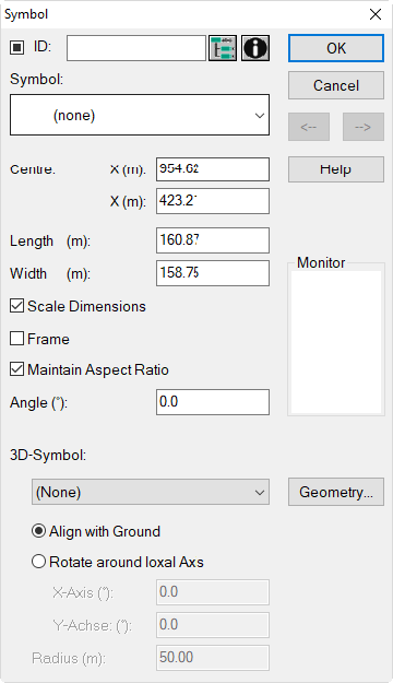
Dialog options
Mark, ID, ObjectTree, INFO
see Dialog Options Name, ID, INFO, ObjectTree, Master in the manual "Introduction to CadnaA"
List Box „Symbol“
The list box on the dialog offers to select a predefined (see below) or a user-defined symbol. A preview of the selected symbol is shown on the monitor.
Note
Note that the assignment of a symbol is based on the language specific symbol name. Therefore, when changing the language setting the symbol selection may no longer be valid (e.g. when using the North-Arrow). After toggling the language of the user-interface reselect the symbol/s via this list box.
Centre/Length/Width
geometry data of the symbol
Scale Dimensions
With this option being active, the size of the symbol in the graphical representation depends on the scale selected/entered.
Frame
toggles on/off the display of a frame
Main Aspect Ratio
When the option „Maintain Aspect Ratio“ is activated, the symbol will always be displayed with the original aspect ratio. Consequently, it will not be distorted when the size of the box is edited.
Angle (°)
Rotation angle from North direction (= 0 °), counterclockwise positive
Suffix for Legend
For the symbols of the type „Legend: Grid ...“ the default suffix „dB“ can be replaced by any other suffix (e.g. „inhabitants“). To achieve this, open the dialog Memo-Window of the respective symbol and define the string variable „Suffix“ and its value (e.g. suffix=inhabitants).
Options for 3D Symbols
The options on the lower part of the dialog Symbol refer to 3D-symbols only.
List Box
The name of 3D-symbols available in the local 3D-symbol library (see menu Tables|Libraries (local)|Symbol 3D Library) are displayed in this list box.
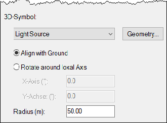
Option „Light Source“
In addition, the 3D-symbol „light source“ is available from the list by default. This enables to place a light source which causes shadows at obstacles. In this case, use the „Geometry“ button to enter coordinates and the input box „Radius“ to specify the radius of the light source.
Button „Geometry“
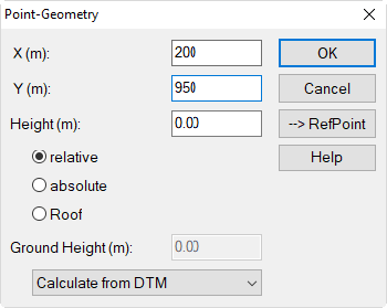
Via this button the height of the 3D-symbol in the 3D-Special view can be set in particular. By default, a relative height of 0 m is defined.
Note
The coordinates x, y on this dialog are not relevant, but only those in the dialog Symbol.
Align with ground/Rotate around local Axis
These options may be used to adapt the 3D-symbol to a sloping ground or in order to rotate it freely:
- Option "Align with ground": When enabled, the local z-direction of the 3D-symbol is based on the terrain slope. The local z-direction corresponds to the surface normal at the local ground point.
- Option "Rotate around local Axis": With these options the 3D-symbol can be rotated around the local x- or y-axis of the 3D-symbol. This enables to rotate 3D-symbols, which have been imported with orthogonal object geometry, in the 3D-Special view around the x- or y-axis.
Global Appearance
The global appearance of symbols (as for „Line“ and „Fill“) are defined via the dialog Options|Appearance (see Object Appearance). The option „Fill“, however, is not available for all types of symbols.
Default Symbols
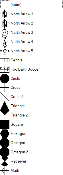
By default, the following symbols are available:
 |
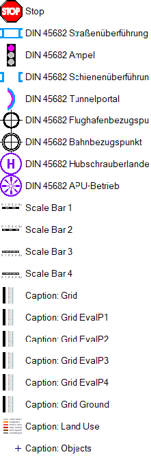 |
*) The display for symbols of type „Legend: Grid EvalP“ depends on the color palette and its settings for the evaluation parameter selected.
Furthermore, at the bottom of the list box „Symbol“, all local color palettes are listed.
Legend: Land Use
On the legend for land uses all long names defined on the dialog Land Use are listed (see Type of Land Use).
Legend: Objects
The object legend all types of objects existing in the present file are shown, provided the option „Show Object Type“ is not disabled (on dialog Options|Appearance, see Object Appearance).
User defined Symbols
In addition, user-defined symbols may be used. User-defined symbols are kept in the library of symbols (see Symbol Library) which will be listed subsequently on the list box.