„Particle Model“ tab
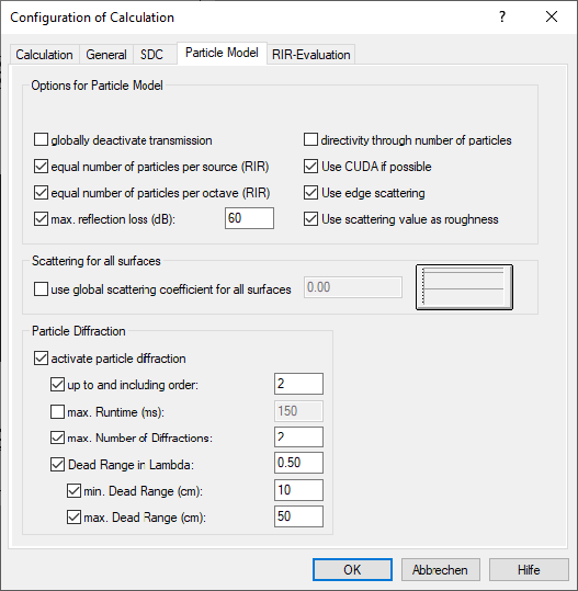
The following additional options apply when the particle model or the combined procedure is selected (in case of the combined procedure "Image Sources --> Particles" just for the part of the particle model).
All of the following options are deactivated by default.
globally deactivate transmission
With this option activated, the sound transmission at obstacles is not considered in the calculation. This holds also when a transmission factor/sound reduction index for obstacles has been entered or referenced from the local/global libraries.
equal number of particles per source / per octave
These two options are available provided the option „... for receivers“ is activated on the „RIR evaluation“ tab.
- equal number of particles per source (RIR): When activated, the same number of particles are generated for each source when calculating the room impulse response.
- equal number of particles per octave (RIA): When activated, the same number of particles is generated in each octave when calculating the room impulse response (default ON).
By both options, an excessive number of iterations can be avoided at low levels when evaluating echograms for the quality criteria T30, T20, T10 and EDT. Otherwise, for low-noise sources or at low levels, a significant lower number of particles would be generated (in this case proportional to the source power), resulting in additional iterations and thus requiring a longer calculation time.
maximum reflection loss (dB)
For the particle model, the maximum reflection loss (in dB) can be entered (default value: 60 dB). Particles which - due to reflection/absorption at the surface of obstacles - exceed the specified reflection loss are no longer traced.
This option prevents for excessive calculation times in situations where the continuing accumulation of reflection losses would not cause any effect on the level (at least, at the default value of 60 dB).
Directivity through number of particles
By activating this option in addition, the directivity at point sources is considered in the calculation by a different number of particles resulting from the directivity index. In this case, all the emitted particles have the same energy. With a high directivity index more particles are radiated into this direction than at a low directivity index.If the option is disabled, the directivity of point sources is taken into account in the particle model or in the particle-based share of the combined method by a varying particle energy. In this case, the same number of particles are radiated into all directions, but having a different energy.
Use CUDA if possible (by default ON)
The calculation procedures „Particles“ and „Image Sources --> Particles“ can take advantage of the parallel computing power of a GPU (Graphic Processing Unit). With the particle model, all features available on the CPU can also be used with CUDA. The statement „if possible“ refers to the check performed by CadnaR regarding the graphics card hardware. For further information, please download our Technical Note „Hardware“ from our website. For CUDA calculations in CadnaR, any open 3D view will be closed automatically in order to reserve the GPU speed entirely for calculations. The CUDA calculation time is saved to a local text block (see Local/global Libraries).
Use edge scattering (by default ON with new projects)
This option, if active, causes scattering of particles up to a distance of half a wavelength from obstacle‘s edges. This enables to include the frequency-dependent scattering effect at edges, in contrast to the purely geometric reflection at obstacles without scattering (if inactive). Studying real scenarios reveals that considering the edge scattering can improve the agreement between calculated and measured results.
Use scattering value as roughness (by default ON with new projects)
With this option active, the numerically entered scattering coefficient at obstacles (i.e. box-type source, box-type obstacle, barrier and PolyMesh) is taken as the scattering coefficient at 1000 Hz. The scattering coefficient for the remaining octave-band frequencies is determined from tabulated data (literature see Literature). Intermediate values of the scattering coefficient are interpolated linearly. When referencing a spectrum of the scattering coefficient in object dialogs, however, this spectrum is used in the calculation.
use global coefficient for all surfaces
If this option is activated, the entered scattering coefficient will be used for any surface in the project, i.e. for all room boundary surfaces and for all object surfaces.
Note
the scattering coefficients assigned to each individual object or for each room boundary surface then are ignored and replaced with the global value for the calculation.
Particle Diffraction, activate
Once the option is activated (default), one or several conditions can be specified, which must be fulfilled to cause diffraction:
- up to and including order: Particles up to and including the specified order are diffracted. For example, with input of 0 (zero) just particles resulting from the direct field are diffracted, while with input of 1 also particles which have once been reflected are diffracted as well (default: 2).
- max. Runtime (ms): Up to this particle runtime (starting from the source) diffracting edges are traced. Edges beyond this maximum runtime are not considered for diffraction calculation (default: 150 ms)
- max. Number of Diffractions: In addition to the maximum runtime, the maximum number of diffractions (diffracting edges) can be defined at which particle diffraction occurs. When activated, this condition is checked for in addition to the - possibly - activated condition „max. Runtime“ (default: 2)
- Dead Range in Lambda: When activated, no further diffraction is allowed in the distance range defined by the wavelength from the diffracting edge (default: 0.5 -> range of half a wavelength).This condition can nevertheless lead to very large ranges at low frequencies. Therefore an absolute range limitation can be entered:
- min. Dead Range (cm): minimum distance from the diffracting edge (default: 10 cm)
- max. Dead Range (cm): maximum distance from the diffracting edge (default: 50 cm)
Literature
- Trevor J. Cox; Peter D'Antonio: Acoustic Absorbers and Diffusers: Theory, Design and Application, 2nd edition, CRC Press 2009.