Receiver
Calculation results are displayed in the dialog Receiver.

Dialog Receiver
Dialog options
- Name, ID, ObjectTree and Memo-Window see Common Input Data
- Coordinates x|y|z: The xy-coordinates refer to the origin. The z-coordinate is the height of the receiver above the room's floor.
Dialog Range „Workplace“
When the option "Receiver is workplace at sound source" is activated the receiver is defined as a workplace. This means that the specified source group (e.g. a machine) is assigned to the receiver.
- Source Group: For a group of sources, the assignment occurs automatically by evaluating the ObjectTree (see ObjectTree). This requires that the sources and the obstacles to be assigned must be in the same group as the receiver itself. In this case, enter in input box „LpA“ at the end of the line „Source Group“ the emission sound pressure level LpA for the entire source group.When having a source group assigned, the sound pressure level at this receiver under semi-free field conditions (direct sound plus ground reflection) is calculated by a pre-calculation taking into account all sources and obstacles within the group. All sources and obstacles not part of this group are deactivated during this pre-calculation.Upon completion of the pre-calculation, the calculated sound pressure level spectrum at this workplace is renormalized in order to obtain the specified emission sound pressure level LpA. The floor is always considered as fully reflective in this case (regardless of the definition of the room boundary surfaces).
Note
the emission sound pressure level can only be used if all sources of the source group have the same operating time. In case of different operating times a warning in the consistency check appears and the LpA-calculation will not be executed.
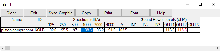
- Source Group LpA from SET-T module: The workplace-related emission sound pressure level LpA of a source group can also be set via a SET-T module (requires option SET). In this case, the string variable "GroupLpaSet" with the ID of the SET-T module to be used defines the Source-Group LpA to be used.
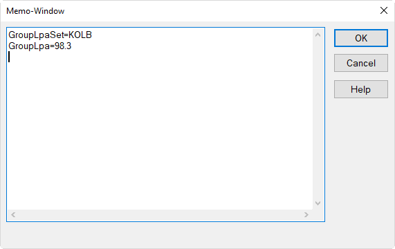
The text variable "GroupLpaSet" refers to the SET-T module with theID "KOLB". After calculation, the source group LpA calculated is addressed to the string variable "GroupLpaSet".
Note
The calculation uses the value of the 1000 Hz octave of the referenced SET-T module as a single value.
Example for a Source Group
This example shows a source group with several obstacles (box-type obstacle square and barriers) and multiple sources (point and area source). The workplace referring to this source group is located inside the same group of the source model:
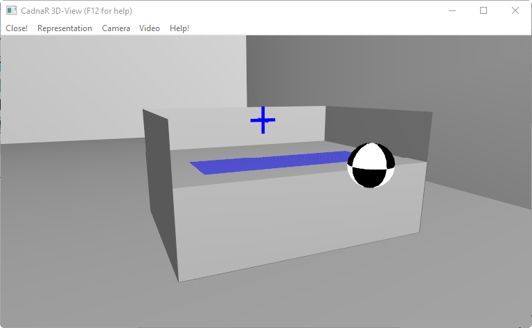 |
model of a machine consisting of a box-type obstacle and barriers and a single point and area source !!! example Path: Files\Manual\Chap 5_9\source group.cni |
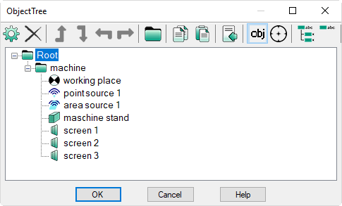 |
structure of the ObjectTree: The receiver representing the workplace is part of the group containing the entire machine model. There may also be several receivers within the source group. |
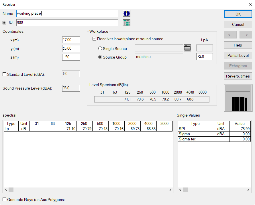 |
As soon as the option „Source Group“ option on the dialog Receiver is selected, the group‘s name appears (here: „machine“) and the corresponding workplace level LpA can be specified. After completion of the calculation of the resulting level and the level spectrum are displayed. |
Standard Level/SPL/Level Spectrum
- Option "Standard Level": After activation of this option a standard level (limiting value) in dB(A) can be entered. In case of an exceedance at this receiver the receiver's symbol is displayed in red on the plan view and on the 3D-view.
- Sound Pressure Level (dBA) / Level Spectrum dB (lin): In this part of the dialog the A-weighted sound pressure level and the linear (unweighted) octave level spectrum at this receiver are displayed.
Bar Chart
graphic showing the shape of the octave band level spectrum. By clicking on the chart, the weighted cycles (lin/A/B/C/D).
Result Tables, spectral/Single Values
The spectral table shows the unweighted (linear) sound pressure level values Lp, as well as the results for the spectral room acoustical parameters, when selected for calculation. In addition, the entered or selected linear noise level spectrum L_N is displayed (see "RIR-Evaluation" tab).
On in the table „Single Values“, the A-weighted sound pressure level SPL, the standard deviation Sigma, the number of iterations, and the non-spectral room acoustic parameters are displayed, when selected for calculation (see "RIR-Evaluation" tab).
Note
Besides displaying the results (per variant, if any) on the dialog Receiver they are also written into variant-specific attributes which can be addressed. In order to access an attribute the variant number gets attached, e.g. LPV03 to access the A-weighted level of the 3rd variant, EDT_2000V05 to access the Early Decay Time at 2 kHz of the 5th variant etc. With no variant number attached the value of the actual variant gets accessed (see Object Attributes).
Option "Generate Rays (as Aux. Polygons)"
Upon activation of this option prior to a level calculation using the image source calculation method the sound rays are displayed in the 2D-graphics up to the specified reflection order. Furthermore, the rays can be displayed on the 3D-view as well (key S).After a calculation the ID of each auxiliary polygon representing a ray shows the partial level, the order of reflection, and whether the ray was subjected to screening (indicated by attached letter S) and whether the receiver is a workplace (indicated by attached letter W).Examples:
- RAY_672_00: ray with partial level 67.2 dB(A), 0th order=direct path (00), not screened
- RAY_568_01S: ray with partial level 56.8 dB(A), 1st order (01), screened
- RAY_434_02_W: ray with partial level 43.4 dB(A), 2nd order (02), receiver is workplace
Button „Virtual Acoustic Camera“
Opens the 3D view with the Virtual Acoustic Camera for the receiver location, see Calculate Virtual Acoustic Camera.
Button „Partial Level“
Clicking this button displays the table Partial Level. The table shows the following columns:
- Name and ID of the source
- Type of source: PQ (point source), LQ (line source), FQ (area source), FV (vertical area source), QQ (box-type source)
- A-weighted sum level in dB(A)
- linear (unweighted) octave band level in dB
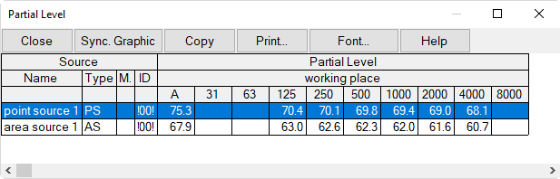
Table Partial Level (via dialog Receiver)
Additional Notes
- For deactivated sources no partial levels are displayed.
- The table Partial Level on the Tables menu, in contrast, shows the partial levels of all sources at all receiver points (see Table Partial Level).
- The number of decimals X displayed in the table can be specified via INI file (section [Main], dBOutPrec=X, see Edit INI-File).
Button "Echogram"
This button is only available with the calculation procedures "Image Sources --> Particles", "Image Sources" or "Particles" and if the option "Calculate Echograms and Decay Curves" on the "RIR-Evaluation" tab has been activated (see Configuration). After clicking the button, the dialog RIR-Evaluation is opened.
see also: Delete Rays (see Delete Rays
Dialog Echogram
In dialog RIR-Evaluation from the time course of the respective immission incoming sound signals smoothed by backward integration RIR-Evaluation is shown. The used class width and number of classes of the timeline depends on the settings in the Configurations, tab "RIR-Evaluation" (see Configuration).
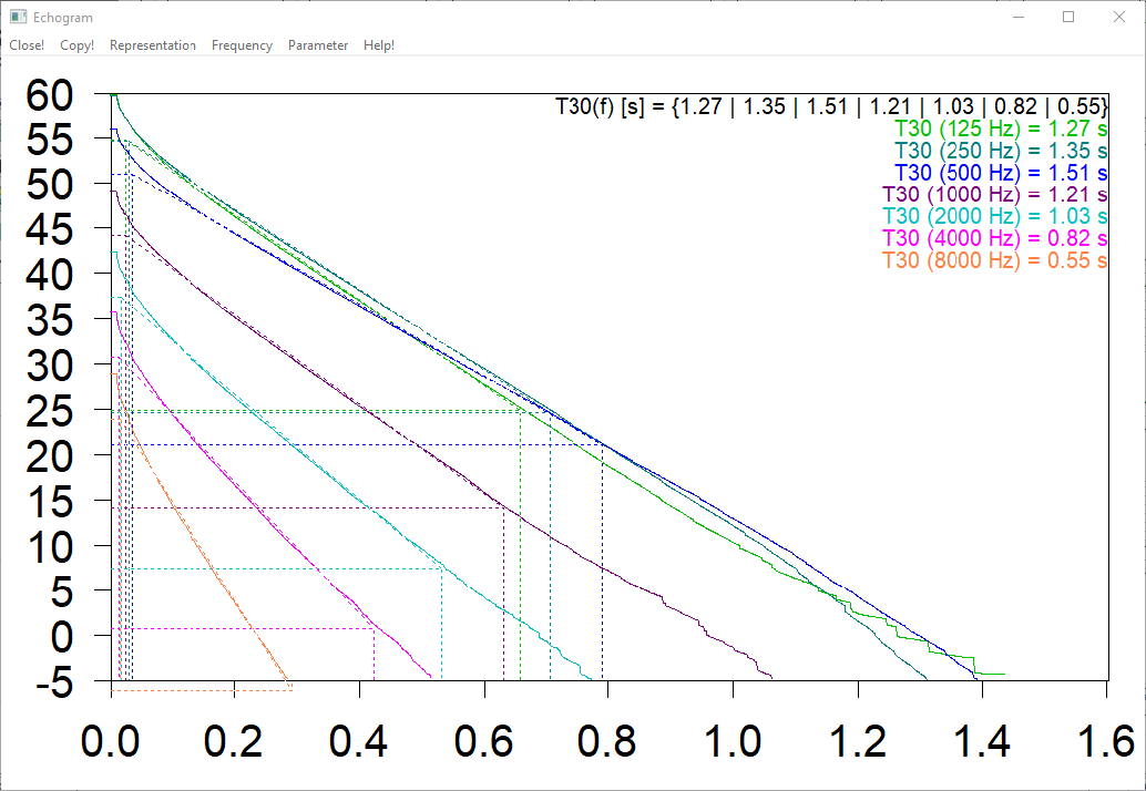
Echogram with regression lines for the evaluation of T30in the frequency range 125 to 8000 Hz (x-axis: in seconds, y-axis in dB).
Menu Commands
- Close: The dialog closes.
- Copy: By clicking on this button the chart will be copied as a meta file in the WINDOWS clipboard. From there, it can for example be inserted into a word processor.
-
Display options:
- Display Echogram (available only when an octave is selected and not the total level, see below)
- Display Decay Curve
- Display Regression Line
- Display Values for Parameter
- Increase Line Width of Decay Curve
- Restrict Level Range
- Common Level Range
-
Frequency Range:
- 31-8000 Hz: Select Octave
- Total: for total level
-
Parameter: For the room acoustical parameters T30, T20, T10, and EDT the respective regression lines are displayed. For T30, T20, T10, the evaluation occurs from -5 dB to -35/-25/-15 dB and for EDT from 0 dB to -10 dB starting with the emission of the source.
Button „Reverberation Times“
This button is only available with the calculation procedures "Image Sources --> Particles", "Image Sources" or "Particles" and if the option "Calculate Echograms and Decay Curves" on the "RIR-Evaluation" tab has been activated (see Configuration). After clicking the button, the dialog Reverberation Times is opened.
Dialog Reverberation Times
On this dialog the reverberation times T30, T20, T10 and EDT resulting from the evaluation of the echogram of the current receiver are shown depending on frequency. Additional settings and descriptions of the menus, see Spatially averaged reverberation time (Receivers + grid).
Dialog Level Spectrum
The Level Spectrum for the receiver is shown in a diagram including NR and NC noise weighting curves:.
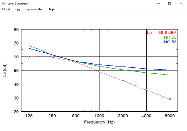
Level spectrum incl. NR and NC noise rating curves according to VDI 2081-1
NR and NC noise weighting curves
At menu Representation, NR and NC noise weighting curves as well as the corresponding single value can be activated / deactivated. For comparison it is possible to show the noise weighting curves NC20 - NC80 / NR20 - NR80.
Representation with A-weighting
At the submenu spectral representation, A-weighting can be added for all displayed curves.
Individual standard deviation (particle model)
For calculation with the particle model, an individual standard deviation for the receiver can be set using the setting a memovariable MAXSIGMA_A. E.g. MAXSIGMA_A=0.5 in the memofield sets the standard deviation for this receiver to 0.5 dB(A).
Individual Noise Level Spectrum (STI calculation)
An individual noise level spectrum per receiver can be entered for the active variant (see Variants). Provided this individual noise level spectrum is defined and the option „prefer noise level from receiver“ is set (see "RIR-Evaluation" tab), then this will be used in the STI calculation for this receiver and for this variant. If no individual noise level spectrum has been defined for a receiver, then the noise level spectrum from the configuration will be used (set or present, if any).
Input
An individual noise level spectrum can be entered in two ways:
- input by using the object attributes NOIIN_31 .. NOIIN_8000 (see Object Attributes). In this case, the user has to make sure that the allocation occurs only for the receivers as intended (see Chapter 6 - Modify Objects).
- Input via the extended object table Receiver: To this end, additional columns for displaying the object attributes NOIIN_31 .. NOIIN_8000 in the table Receiver are defined (see Editing Object Tables).After enlarging the table by additional columns making reference to the attributes - as mentioned above - the individual noise level spectra can then be entered for each receiver.
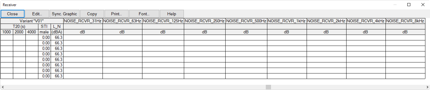
Receiver Table: default table extended by 9 columns to enter a individual noise level spectrum per receiver