Vertical PolyMesh
The vertical PolyMesh is a screening object with a closed simple border polygon in the vertical plane, which may also contain openings. The plane is defined by a single segment of lower and upper height, which includes coplanar the boundary polygon and possibly inner loops („holes“). The vertical PolyMesh may have sound absorbing, scattering and transmitting properties.
This object is used when importing object geometries from external software - e.g. from SketchUp (see Sketchup SKP (*.skp)) - into CadnaR in order to generate a screening object having openings inside its surface.
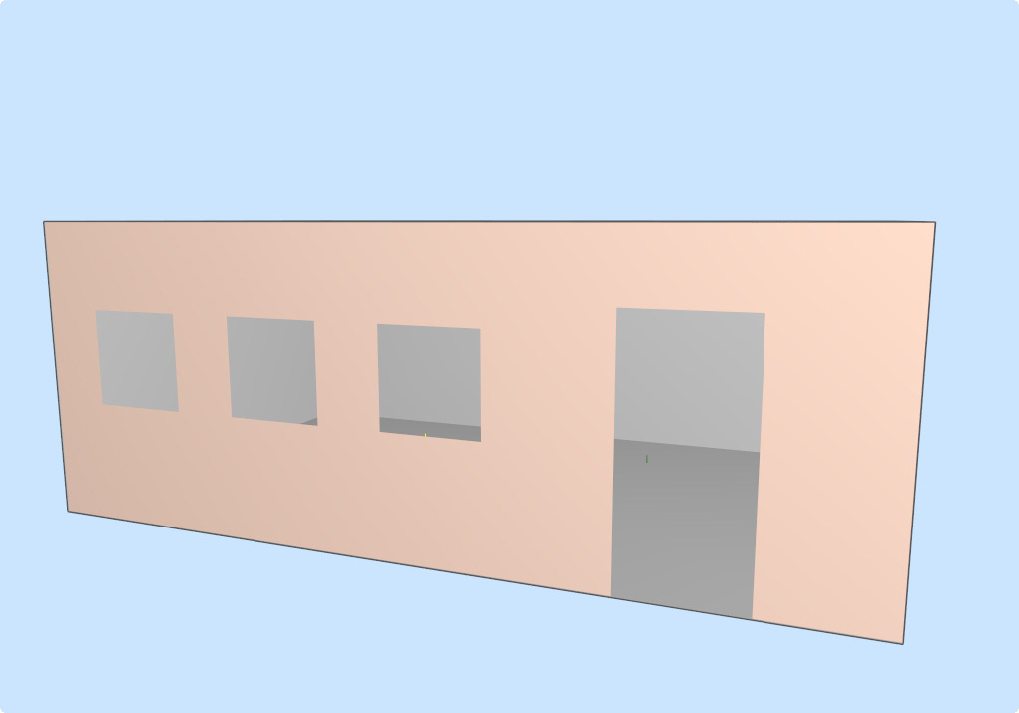
vertical PolyMeshes with openings imported from SketchUp
The vertical PolyMesh can only be used with the Particle Model (and with the particle model fraction of the hybrid method, see "Calculation" tab). With calculations using image sources, the object is ignored.
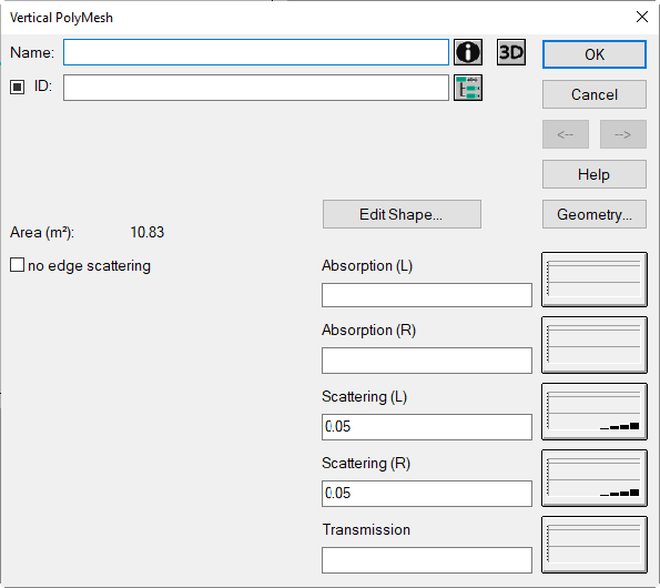
Dialog Vertical PolyMesh
Dialog options
- Name, ID, ObjectTree and Memo-Window see Common Input Data
- Area: surface area of one side of the vertical Polymesh (in m²)
- „Edit Shape“ button: see below in this chapter
- Buttons „Absorption/Scattering/Transmission“: see Common Input Data - Obstacles
Note
The terms "L/R" refer to the left or right side of the screen, as seen from the first to the last point of the barrier's polygon.
- Option „no edge scattering“ and button „3D“: see Common Input Data - Obstacles
- Button Geometry: see Common Input Data - Geometry
Edit Shape
This button opens the Shape Editor dialog, enabling to define
- openings within the current vertical PolyMesh or
- an arbitrarily shaped boundary polygon (instead of the default vertical-rectangular one).
For details of the procedure in both cases, see the following.
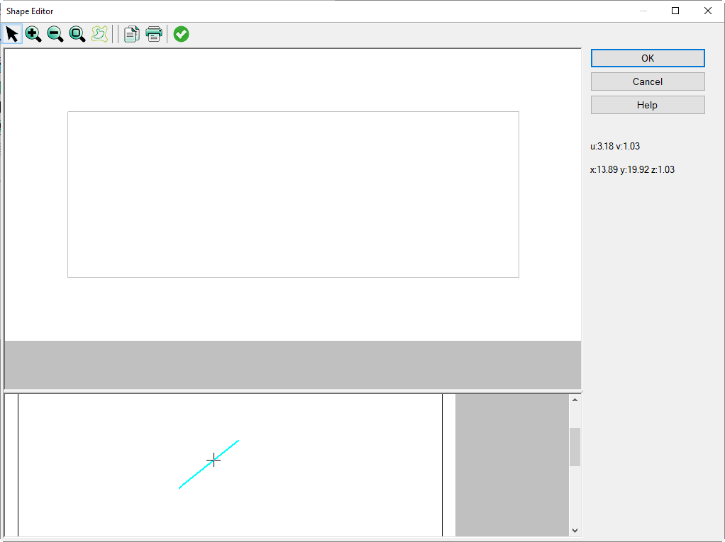
Shape Editor dialog
The dialog consists of a specific toolbar, a status bar and the following views of the selected vertical PolyMesh:
- top: front view (right side, when looking from first to last point),
- bottom: top view.
The scale of the front view can be changed using the toolbar (Zoom in/out, Zoom to Limits).
When having entered an object, the object dialog can be accessed as usual (double-click on object border in edit mode or click with the right mouse button in input mode).
Local Coordinate System u, v
On the status bar, the local coordinates u (increasing to the right) and v (increasing upwards) are displayed in a local coordinate system whose origin (u, v)=(0, 0) is located in the lower left corner of the front view (minimum of the zmin coordinates of both polygon points). When entering objects using the mouse or the keyboard, the object coordinates refer to the local coordinate system (u, v).
In addition, the global coordinates x,y,z are displayed below, which correspond to the data displayed on the Geometry dialog.
Coordinated Display of the Mouse Pointer
When the mouse pointer is moved in the front view, CadnaR shows the corresponding point on the top view. This feature enables to figure out the current cursor position in the u-v plane. The input data of the entered objects can be edited by double clicking onto the object’s border.
Context Menu
For entered objects, a context menu with the following commands is available:
- Edit (see Context Menu)
- Delete (see Delete)
- Duplicate (see Duplicate).
Furthermore, all options for graphical editing of objects can also be used (see Editing Objects graphically).
Symbol Bar of the Shape Editor
The following objects and features are available:
 |
Select Edit Mode |
 |
Zoom in |
 |
Zoom out |
 |
Zoom to Limits |
 |
enter contour line |
 |
copy to clipboard |
 |
open Print dialog |
 |
save present settings and close dialog |
Defining Openings
Select the object „Contour Line“ on the toolbar using the mouse and enter the edges of the opening according to their location. Clicking the right mouse button will automatically close the polygon.
All options for graphical editing of objects can be used (see Editing Objects graphically). Alternatively, the coordinates can be entered via the keyboard (see Inserting Objects).
Editing Boundary Polygon
Select the object „Contour Line“ on the toolbar using the mouse and enter the edges of the new boundary polygon of the vertical PolyMesh to be used. Open the edit dialog of the contour line (in edit mode by double-clicking on its border or in the input mode via its context menu) and activate the option „Boundary Polygon“.
Note
Just a single boundary polygon can be used at time. If more than one border polygon is entered, CadnaR will use the last one entered (see below).
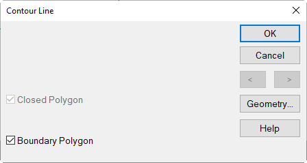
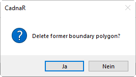
Close the Contour Line dialog and the Shape Editor dialog with OK. You will prompted whether the vertical PolyMesh should be adapted to the new border polygon:
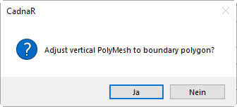
By confirming with „Yes“, the entered polygon forms the new boundary polygon of the object.
If more than one contour line is entered, each with the option „Boundary Polygon“ active, after confirmation of the query only the last one entered will be preserved: