Image Source Model
With this procedure, the reflection at room surfaces and at obstacles (as well as at reflective sources) is modeled by rays, the path of which is pursued and determined step by step for every single ray and for every reflection point. This requires to check for any ray radiated by the source whether this ray - also after being reflected n-times at surfaces - hits a receiver or a grid point. The location of the image sources is obtained by determining the reflection point and the angle of incidence of the respective ray at a reflector. From the position and orientation of the reflector with respect to the ray’s path the angle of reflection is evaluated, possibly decreased due to the absorptive properties of the reflector. Subsequently, the ray’s path is pursued recursively up to the specified order of reflection. With obstacles located in the ray’s path, the ray path having the smallest path length difference around the arrangement of obstacles in a vertical and/or horizontal plane determines the barrier attenuation.
Example
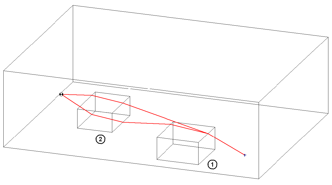
Found diffracted ray paths around two obstacles (obstacle 1 on the ground, obstacle 2 floating above the ground, when just the option "vertical diffraction" is activated (here: 2 paths found, the shortest path is used).
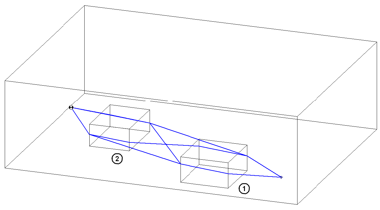
Found diffracted ray paths around two obstacles (obstacle 1 on the ground, obstacle 2 floating above the ground, when just the option "horizontal diffraction" is activated (here: 4 paths found, the shortest path is used).
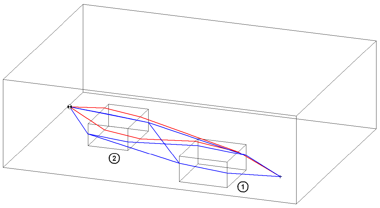
Found diffracted ray paths around two obstacles (obstacle 1 on the ground, obstacle 2 floating above the ground, when both options are activated (here: 6 paths found (vertical: red, horizontal: blue), the shortest path is used).
In any case, the ray path having the smallest path length difference compared with the direct path determines the screening effect of the encountered arrangement of obstacles.
The image source procedure is suitable for any kind of floor plan (i.e. also for non-rectangular) and for any arrangement of sources and obstacles. The procedure requires a reasonable calculation time with higher orders of reflection, though, since many ray paths have to be examined and rejected - if necessary - in case these do not coincide with a receiver point or grid point.
Calculation
For the calculation of the various attenuation terms the procedures of ISO 9613-1 and -2 are applied.
Note
The designations used for the attenuation terms below appear also as column designators on the protocol (see Protocol).
Divergence
The attenuation due to geometrical divergence calculates from:
\(A_{div}=10 \lg (4 \pi \frac{d^2}{d_0^2}) dB\)
where
- d: straight line distance from source to receiver, in m
- d0 = 1 m
Air Absorption
The attenuation due to air absorption calculates from:
\(A_{atm}=\alpha d / 1000 dB\)
where
- α: absorption coefficient of air accord. to ISO 9613-1, in dB/km (octave center frequency)
- d: straight line distance from source to receiver, in m
Barrier Attenuation
The barrier attenuation Abar calculates from:
\(A_{bar}=D_Z = 10 \lg [3+(\frac{40}{\lambda})C_3 z] dB\)
where
\(C_3=1\) for single diffraction
\(C_3=\frac{1+(\frac{5\lambda}{e})^2}{\frac{1}{3}+(\frac{5\lambda}{e})^2}\) for more than a single diffracting edge
with
\(1 \leq C_3 \leq 3\)
and the path length difference z:
\(z = (d_{ss}+d_{sr}+e)-d\)
where
-
dss: distance from source to the first screening edge
-
dsr: distance from the last screening edge to the receiver
-
e: distance from source to the first to the last screening edge
-
d: straight line distance from source to receiver
Reflection Loss
The reflection loss RLi in dB for a single reflection at a reflector i results from the absorption coefficient αi according to:
\(RV_i = - 10 \lg(1-\alpha_i)dB\)
For a number of reflections n the total reflection loss RL results from:
\(RV=\sum_{i=1}^{n}RV_i\)
Application Notes
- order of reflection: With the object arrangement (sources and obstacles) given, the specified order of reflection determines the computation time required. In order to save computation time by reducing the order of reflection, the absorption characteristics of the room surfaces are relevant in particular: The higher the mean absorption coefficient of the room surfaces, the lower the maximum order of reflection can be used to achieve a constant level. In the extreme case, with entirely absorbing room surfaces (Alpha = 1), a constant level results already at an order of reflection 0 (i.e. direct sound only).
Example
Path: Files/Tutorial/Chap 7_1
| levels in a room with average absorption (mean absorption Alpha = 0.5) |
levels in a room with none absorption(mean absorption Alpha = 0) |
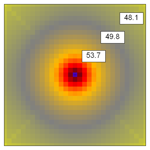 ... up to 5th order of reflection |
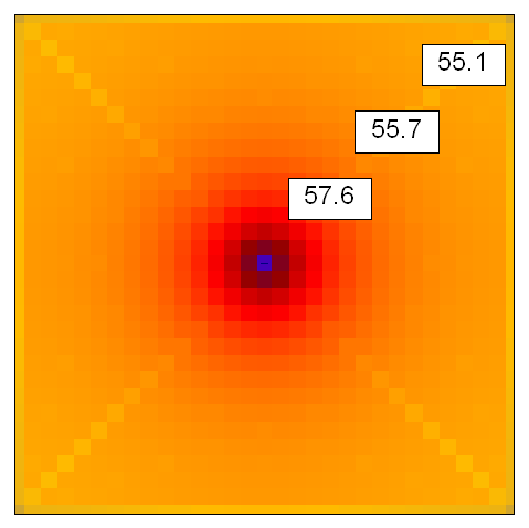 ... up to 5th order of reflection |
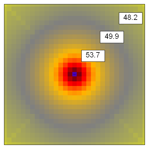 ... up to 10th order of reflection |
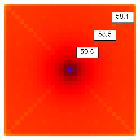 ... up to 10th order of reflection |
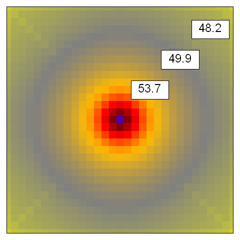 ... up to 20th order of reflection |
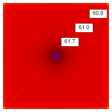 ... up to 20th order of reflection |
- Screening (vertical/horizontal diffraction): Per default, both options are activated causing that both, the vertical and the horizontal plane are examined to determine the shortest path length difference. This setting should be kept kept for normal arrangements of obstacles and leads, in most cases, to acceptable computation times.In some special situations, it may make sense to change this default setting in order to reduce the computation time. For example, the arrangement of obstacles consists of many objects extending from the floor while in between just a few empty lanes remain, the option „horizontal diffraction“ may be deactivated since the shortest path length difference is determined by the ray path across the objects. The option „vertical diffraction“ may, however, be deactivated in situations with obstacles extending from floor to ceiling (walls“) since the shortest path length difference is determined by the ray path in the horizontal plane.