PolyMesh
The object "PolyMesh" represents a special object offering to define an arbitrarily shaped and - where appropriate - non-planar screening/reflecting/transmitting surface in 3-dimensional space.
Note that the PolyMesh can only be used with the Particle Model in CadnaR (see Particle Model and Configuration). Furthermore, it cannot be used to generate vertical triangles or undercuts (i.e. two or more screening surfaces in z direction).
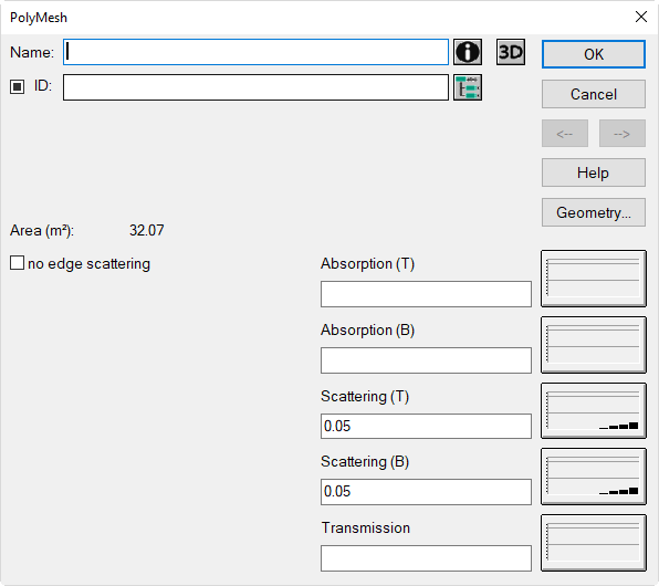
Dialog PolyMesh
Dialog options
- Name, ID, ObjectTree and Memo-Window see Common Input Data
- Area: surface area of one side of the PolyMesh (in m²)
- Buttons „Absorption/Scattering/Transmission“: see Common Input Data - Obstacles
Note
The terms "T/B" refer to the top or bottom edge of the PolyMesh.
-
Option „no edge scattering“ and button „3D“: see Common Input Data - Obstacles
-
Button Geometry: see Common Input Data - Geometry
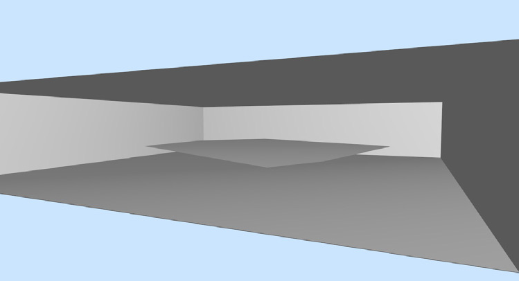 |
PolyMesh with arbitrarily edge contour, but with constant height |
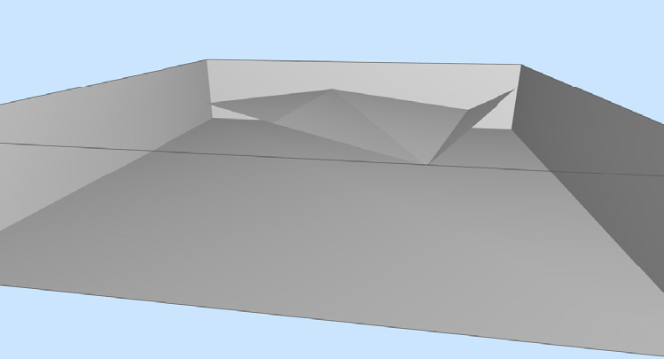 |
PolyMesh with arbitrarily edge contour and individual height at each polygon point |
Application
Combined effect in conjunction with height points and contour lines
The PolyMesh can be applied in conjunction with the objects „Height Point“ (see Height Point) and „Contour Line“ (see Contour Line) to generate arbitrarily shaped screening/reflecting/transmitting surfaces in 3-dimensional space.
Proceed using these steps:
- First, enter the border of the screening surface using the object „PolyMesh“.
- Edit - if required - the height at each polygon point via the dialog Geometry.
- Select the object „Height Point“ to define additional height points inside the PolyMesh‘s polygon.
- Select the object „Contour Line“ to define additional height polygons inside the PolyMesh‘s polygon.
Note
The objects „Height Point“ and „Contour Line“ have initially - after having been entered - no acoustical relevance and are, therefore, not shown on the 3D-view and are not taken into account in a calculation. This is not an error, but due to the properties of this object.
Context Menu CommandsGroup PolyMeshUngroup PolymeshBreak polymesh into pieces
see Context Menu, Group / Ungroup PolyMesh, Break PolyMesh into Pieces.
Triangulated Lines
The triangulation between the nodes of PolyMesh occurs after having entered the object. After additional input of inner height points and contours lines the triangulation occurs after selection of the Group PolyMesh command. The display of the triangulated lines can be deactivated (see Appearance).