Calculation according to VDI 3760
The sound decay curve according to VDI 3760Literature is calculated for a diagonal path in the room. On the CadnaR main window, this path starts in the lower left corner of the room at a distance of 1.5 meters in all three directions from the walls (source coordinates (x,y,z) = (1,5; 1,5; 1,5) m) and ends in the upper right corner. The calculation of receiver levels is carried out at predefined distances (sequence of distances).
For every receiver point the level contribution of the rays reflected at room surfaces is calculated applying the principle of image sources with scattering and damping according to Kuttruff and Jovicic. Thus, up to 50,000 energy fractions are summed up per receiver point, depending on the absorption coefficient of the room surfaces. The coefficient of absorption is assumed as being independent of the angle of incidence. Finally, all energy fractions are summed up without considering the phase relation between different wave components. The sound decay curve (SDC) results as a diagram and in tabulated form.
The characteristic quantities used to assess the acoustical quality of the room according to VDI 3760, the level excess above free-field level in dB (DLf) and the level reduction per distance doubling in dB (DL2), are calculated for all frequency bands as also the total level based on a reference spectrum. This allows a check on whether a requirement regarding a minimum level reduction per distance doubling (e.g. of 4 dB) at certain octaves (e.g. at 500, 1000, 2000 and 4000 Hz) is met.
Note
For calculations according to VDI 3760 no rays to the receiver points can be displayed (see Receiver, option „Generate Rays (as Auxiliary Polygons)“) since this method does not apply ray tracing in the room’s space.
Calculation
Density of Scattering Objects
\(q=\frac{S_S}{4V}=\frac{1}{l_m}\)
where
-
Ss: total surface of scattering objects [m²]
-
V: room volume [m³]
-
lm: average free path length [m]
Note
The density of scattering objects is a major influence for sound propagation at large distances (> 20 m). For this reason, the parameters DLf and DL2 for the middle region (5 m < r < = 16 m) are affected only to a minor extent.
Energy Density of the Direct Sound
The energy density of the direct sound due to scattering is:
\(E_d(r)=\frac{P}{4\pi cr^2}e^{-(q+m)r}\)
where
-
P: sound power of the source [W]
-
q: fitting density [1/m]
-
c: velocity of sound [m/s]
-
r: distance source-receiver [m]
-
m: damping coefficient of air [-],
-
with \(m*10^3=\frac{\alpha_L}{10 \lg e}\) where αL: atmosph. attenuation coeff. accord. to ISO 9613-1 in dB/km
Energy Density of the Scattered Sound
Energy density of the scattered sound:
\(E_s(r)=\frac{3qP}{4\pi c r}e^{-r\sqrt{rqa}}\)
where
\(a=b+\alpha'_sq+m\)
Here α’s is the mean absorption exponent of the scattering objects:
\(\alpha'_s = - \ln(1-\alpha_s)\)
where αs: mean absorption coefficient of the scattering objects
The parameter b describes the energy loss due to absorption at the ceiling and the floor of the room:
\(b=b(\alpha_{\text{Boden}})+b(\alpha_{\text{Decke}})\)
It calculates depending on the room height H - for each, the ceiling and the floor - according to:
-
qH<1:

-
qH>=1:
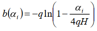
where
- α’: mean absorption exponent floor-ceiling
These equations hold for an infinite room in the xy plane.
Room with finite Dimensions
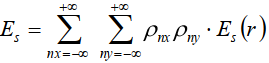
In order to obtain the energy density in a finite room in xy plane, the room is reflected along its room surfaces up to the specified order of reflection. From the location of the image sources the distances and the room surfaces cut by the ray having the reflection coefficients ρnx, ρny, ρnz are determined.
-
for the direct sound energy subjected to scattering:

-
for the scattered sound energy of all image sources:
-
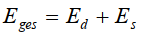
sum:
or expressed as a level difference LpA-LwA:
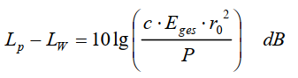
with r0 = 1 m
Note
The room surfaces are the only reflectors taken into account in the procedure according to VDI 3760. Consequently, obstacles (like box-type source, box-type obstacle or barrier) do not cause a screening effect using this calculation method.
Sound Level Distribution
The obtained sound decay curve is used to calculate the spatial level distribution by reducing the sound power level of every source as given by the SDC-curve and by summing up all contributions energetically on the grid. Line and area sources are segmented and replaced by component point sources.
Literature
VDI 3760:1996-02, English Title: Computation and measurement of sound propagation in workrooms (available in German only), see http://www.beuth.de