Room

On the dialog Room Parameters the room dimensions are entered, the sound absorbing properties of the room surfaces and the fitting density are specified. The fitting density is required to the estimate the scattered acoustical energy when calculating the sound decay curve according to the procedure in VDI 3760 guideline.
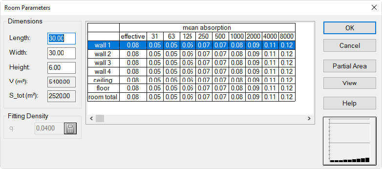
Dialog Room Properties
Dimensions
- Length/Width/Height: Enter the dimensions of the room (in meters). The room height is the acoustically relevant height, e.g reaching to the lower edge of an absorbing ceiling. The plenum height of an absorbing ceiling is taken into account when calculating the effective room volume within the calculation.
- Volume V, Total Surface Area S_tot: The gross room volume (in m³) and the total surface area (in m²) of all room surfaces. These values do not consider the volume of obstacles or the room surface covered by obstacles. When inserting obstacles and when subdividing the room (e.g. by barriers from floor to ceiling) this volume, therefore, does no longer match the free volume.
The basic room in CadnaR has a rectangular shape where the origin (x, y) = (0, 0) is located in the left lower corner of the room. Non-rectangular room shapes can be modeled by entering barriers (see Barrier) and box-type-obstacles (see Box-Type Obstacle) as dividing walls or blocks. Further, the object „PolyMesh“ (see PolyMesh) can be used to model any kind of roof shape. All these objects are laying inside the outer box making up the basic room.
This means:
- The length L corresponds with the maximum coordinate in x direction.
- The width B corresponds with the maximum coordinate in y direction.
- The height H corresponds with the maximum coordinate in z direction.
The default values are L/B/H = 30/30/6 m.
Fitting Density
The fitting density Q in the room can either be entered or alternatively be selected from a predefined list or calculated from geometrical data. Click the calculator symbol  for the latter options.
Note
The fitting density is relevant for the calculation method „VDI 3760“ only.
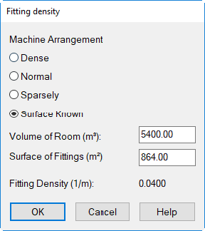
Dialog Fitting Density
The fitting density q is applied according to the definition by Kuttruff. The fitting density has an essential effect in conjunction with long distances (larger than 20 m). The characteristic values relating to intermediate distances are influenced only to a lower extent by the room size.
As an approximation, the fitting density q can be calculated from the machine occupancy in a room. Click the fitting density symbol. This approximative calculation holds for fitting densities at room heights not being larger than twice the average height of fittings.
| Option | Percentage of the Room's Floor Area |
| dense | more than 50 % covered |
| normal | 20 to 50 % covered |
| sparsely | less than 20 % covered |
| surface known | With this option selected, values for the room volume and the surface of fittings can be entered. In special, a room volume differing from the room dimensions (length/width/height) may be entered in case of non-rectangular rooms (e.g. with shed roofs or domes). The surface of fittings corresponds to the surface of all objects in the room assuming all objects being replaced by boxes (cuboids). |
Table with Room Surfaces
In this table, the mean absorption coefficients for each of the six room surfaces (based on the absorption coefficients of all relevant sub-surfaces), the absorption of fittings (only for the calculation method "VDI 3760") and the mean absorption coefficients of the entire room are displayed.
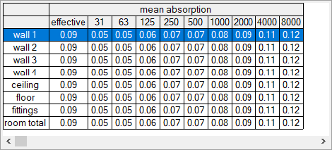
A double-click into a table opens the table Partial Areas. After double-clicking into a row of the table Partial Areas a sound absorbing construction can be selected from the database.
- column "effective": Based on the values shown in line "room total" it can be assessed whether the - in Germany - required minimum value of 0.3 is met or not. If a value in column "effective" is displayed in parentheses, this indicates that not all values are available in the absorption spectra of this room surface.
Table Partial Areas
Double-clicking into the table in dialog Room Parameters or clicking the button „Partial Area“ opens the Partial Areas table.
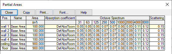
Dialog Partial Areas
The Partial Areas table lists all room surfaces with all their respective partial areas. On the table, partial areas can be edited, inserted or deleted.
- Edit a Partial Area: A double-click into a table row opens the respective dialog Partial Area. As far as having accessed the dialog Partial Area via the table Partial Areas you may switch via the arrow keys ->|<- between the different partial areas.
- Assigning a new Partial Area to a Room Surface: Via the context menu of the table a new partial area can be inserted. Then, double-click in this new row and assign it to a room surface be selecting from the list box „Position“.
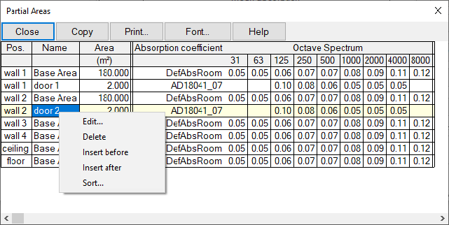
Dialog Partial Areas with two doors inserted: door 1 into wall 1, door 2 into wall 2
Partial Areas realized with CadnaR objects
Note
Depending on the selected calculation method (e.g. particle model) it may be useful to avoid the creation of partial areas within this table and to realize the partial areas as CadnaR objects (e.g. thin box type obstacles) instead.
-
Sequence of Partial Areas: The sequence of partial areas in the list of partial areas is relevant.
-
Absorbing baffles in front of flat absorbers: Arranging absorbing products upon each other, the calculation of the absorption coefficient of the combined construction - e.g. with absorbing baffles in front of flat absorbers - accounts for the combined absorbing effect an acoustically correct way.
-
Overlapping of partial areas: For example, assume three partial areas on room surface "wall 1" are overlapping due to the specified coordinates. In this case the following rules apply:- The partial area in the most upper row in the table (i.e. "partial area 1") is the undermost, rear layer. This means it is placed onto the rear wall or ceiling.- The partial area at the second place (i.e. "partial area 2" below "partial area 1" in the table) is the intermediate layer.- The partial area at the third place (i.e. "partial area 3" below the "partial area 2" in the table) is located on the room side, so, being the topmost layer.- Assume the topmost partial area 3 has the status "closed" assigned to. In this case, the respective absorption coefficient applies to the overlapping area. When the topmost partial area 3 has the status "open" assigned to, the absorption coefficient of the surface will become increased due to the absorption by this layer.
-
Remaining Area: When the sum of all partial areas assigned to a room surface is smaller than the total room surface, the remaining area receives the default absorption coefficient for an acoustically hard reflecting surface.
-
View partial areas: The state of acoustic treatment on each partial area can be checked via the front view on each room surface (by clicking the button "View" on dialog Room Parameters).
-
Dialog Partial Area
On the dialog Partial Area the geometry data for every room surface is edited. Further, sound absorbing products and constructions are selected via this dialog from the local or global library of absorptions.
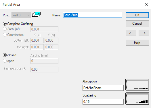
Dialog Partial Area
Scattering coefficients of partial areas
Note
Only the scattering coefficient of the main surfaces (wall 1-4, ceiling, floor) are used for the calculation. If additional partial areas have been entered, scattering coefficients can be assigned to them as well, but these are not taken into account for the calculation. There is also no (possibly area-weighted) averaging of the scattering coefficient over all partial areas of a main surface.
Position
The colored area in the room pictograph indicates the room surface selected (also for the absorption due to room fittings).
- Name: designation of the partial area (e.g. location referring to paper plan)
Outfitting
- Complete Outfitting: In case the room surface is totally covered just by a single product (or construction), the entire area gets the corresponding absorption spectrum assigned. For all base areas the setting „complete outfitting“ is fix.By defining further partial areas (in m ²) or by specifying coordinates within this room surface causes the spectrum marked by the option "Complete Outfitting" to just refer to the remaining area. When a partial area with option "Complete Outfitting" active is a closed surface, all other absorbers behind this surface are not effective any longer (standing below the first area for the same corresponding room surface). These areas are "hidden" by the construction having a closed surface.
- Area in m²: Enter the area (in m²) for the respective partial area. Also in case of area like systems - e.g with absorbing baffle construction - this area is always the projection of the absorber construction onto the respective room surface.
- Coordinates: After activating this option, the xy coordinates for this partial area can be entered. The coordinates refer a view when looking from the interior onto the room surface. Thus, for the ceiling the x coordinate is the common border with wall 3 and the y coordinate is the common border with wall 4.
- open/closed: When having selected a product/construction form the database it is indicated here whether a closed construction (e.g. from ceiling tiles) or an open system (e.g. absorbing baffles) is concerned.
- Air Gap (mm): For open constructions located in front of another absorbing product (e.g. absorbing baffles in front of absorbing ceiling) the absorption coefficient is calculated for the entire construction correctly. For open systems the air gap (in mm) can be specified in the dialog. This air gap is taken into account with respect to the room's volume when calculating the reverberation time.
- Elements/m²: This parameters specifies the density of single absorbers in an arrangement (e.g. parallel distance of absorbing baffles, to centers, or with single absorbers).
Selecting an absorption spectrum
Clicking on the „Absorption“ button provides access to the local or - while holding down the SHIFT key - to the global library of absorptions.
Selecting a scattering spectrum
Clicking on the „Scattering“ button provides access to the local or - while holding down the SHIFT key - to the global library of absorptions.
Button „View“
When clicking this button the currently selected partial area is displayed (e.g. wall 1) in front view.
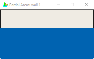
Front View of „Partial areas: wall 1“
The shown view refers to the front view for walls when looking from the interior onto the respective wall area. The numbering is counter-clockwise starting from wall 1 at the bottom.
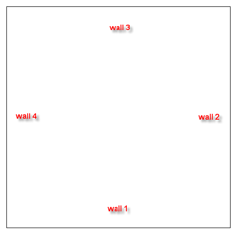
The orientation for both, the ceiling and the floor, refers to the view achieved when the observer - while standing with his back to wall 1 - is looking upwards to the ceiling or downwards to the floor. The origin (x,y)=(0,0) in any case is in the lower left corner when looking onto the respective surface.
This option can be used to check for the distribution of partial areas on each room surface. To this end, all partial areas are shown in the front view with their respective coordinates in a correct aspect ratio of the two surface coordinates. The prevailing mean absorption coefficient is represented by the following colors:
| Absorption | Color |
| lower frequency range | red |
| middle frequency range | green |
| higher frequency range | blue |
| broad band absorption (absorp. coeff. = 1) | black |
| without absorption ("hard" surface) | white |
The above colors ensure that - either with B&W or with color representation - the areas are getting darker with an increasing absorption coefficient. In case a partial area has been entered by using its area (in m²), but not by using the coordinates of its corner points, this is sufficient for the calculation of the reverberation time and the sound propagation according to VDI 3760. The absorption coefficient of this area is referred to the entire surface causing the equivalent absorption area to increase and to be displayed accordingly when viewing the partial areas.
When partial areas overlap partially or totally the representation of the overlapping area depends whether the most inwards located partial area is an open or closed construction.
Absorption diagram
The spectrum diagram on the Room Parameters dialog shows the mean absorption coefficient in octave bands of the selected room surface.