Symbols (2D) and 3D-Symbols
There are two local libraries for symbols in CadnaR:
- (normal) symbols: This kind of symbol is displayed in the 2D plan view, but not on the 3D-Special view.
- 3D symbols: This kind of symbol is displayed in the 2D plan view just by a frame, but not with its contents. In contrast, 3D symbols are displayed in the 3D special view (see 3D-View).
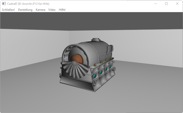
3D-Special view showing a 3D-symbol (generator)
Symbols (2D)
Via Tables|Libraries (local)|Symbol Library user-defined symbols can be imported which can be addressed using the object Symbol on the toolbox. This feature has the advantage that the full resolution of an image is used, independent of the scale. For a symbol the color, the rotation angle and the procedure for adjusting the scale factor can be specified.
Creating a user-defined 2D-symbol
Open a new CadnaR file and create the desired picture by using the auxiliary polygon. Proceed as follows:
- Draw a symbol in CadnaR, for example, using auxiliary polygons.
- Shift the object to the lower left corner of the room (see Transformation).
- Adjust the room‘s floor area to the symbol‘s size (menu Options|Room, see Room) and save the symbol as new CadnaR file.
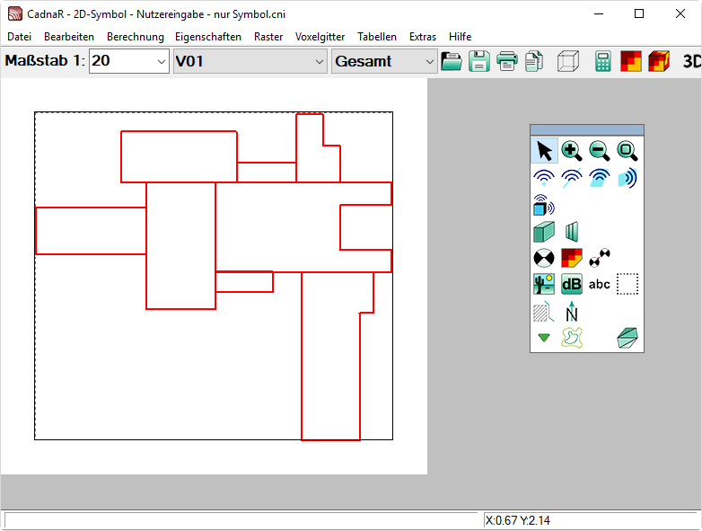
A symbol made of auxiliary polygons
- Insert a new line in Tables|Libraries (local)|Symbol Library.
- Double-click into the new line to open the dialog Library Symbol.
- Enter a name for the symbol to be imported. This name will be displayed on the list box of the dialog Symbol (see Symbol).
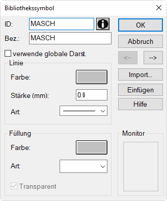
- Click on the „Import" button and select the CadnaR file containing the symbol.
- Close the dialog Library Symbol with OK.
- Select the object „Symbol“ from the toolbox and drag a frame at a location in the project file.
- Select from the list box on the Symbol dialog the name of the symbol. The image will appear in the monitor window.
- After having specified all options close the dialog by OK.
Now, the symbol is placed into the graphics.
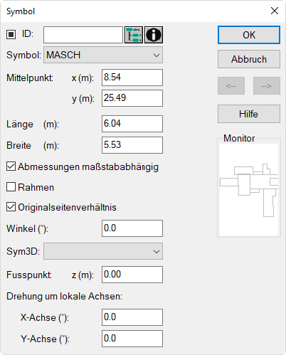
Color and line width of the symbols
There are two ways to assign the color and line width to user-defined symbols.
-
The first possibility is to define the appearance in the original CadnaR file which contains the image. Either via menu File|Appearance|Aux. Polygon as a global setting or directly on the dialog Aux. Polygon. If the option „Use Global Properties“ is deactivated on the dialog Aux. Polygon the appearance of that object can just be changed via the object‘s dialog. These settings are then addressed to this image and cannot be altered within another project file containing this symbol.
-
If, in the original file, the option „Use Global Properties“ is activated the color and line width of the image is adopted to the project file‘s settings in which it is inserted, provided that this option has been activated in the dialog Library Symbol. Otherwise the settings can still be adjusted individually on this dialog.
3D Symbol Library
The 3D symbol library in CadnaR is next to the library for normal symbols (see menu Tables|Libraries (local)|Symbol Library 3D). 3D symbols can be imported by the user to this library and by edited using the settings for 3D symbols on the Symbol dialog (see Symbol). 3D symbols are just displayed on the 3D-Special view.
Inserting a new 3D symbol
Add a new line (via the context menu or using the INS key) via menu Tables|Libraries (local)|Symbol Library 3D. Double-click into the inserted line to open the Library Symbol 3D dialog.
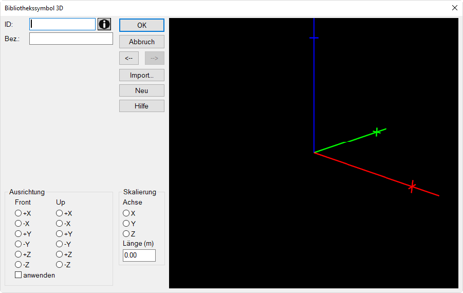
3D Symbol Library dialog (with the coordinate axes XYZ = RGB)
Note
On the Internet, royalty free 3D object files are available (see e.g. http://tf3dm.com or http://archive3d.net). Ensure in each case, however, whether 3D object data can be used royalty free. DataKustik explicitly points out that respecting the license rights of object data owners is the sole responsibility of the CadnaR user himself.
Dialog options
ID / Name
The ID entered will appear in the list box of 3D symbols on the Symbol dialog.
Button „Import“
Clicking this button opens a dialog to select an OBJ file (file extension *.obj) displays. After loading an OBJ file, the 3D object is displayed in the preview window of the dialog Library Symbol 3D including its coordinate axes XYZ.
Note
In order to convert other types of 3D mesh formats into the OBJ format, if necessary, an external 3D mesh processor has to be installed. MeshLab is a suitable processor under the General Public License (GPL), see http://meshlab.sourceforge.net.
Alignment
Via the dialog range „Alignment“ based on the default orientation of the imported 3D object it is specified how the object is displayed in CadnaR. Specify the direction of the coordinate axes for front and up (each offering the options +X, -X, +Y, -Y, +Z, -Z).
For example, Front:+X specifies that the x coordinate of the object geometry is to be rotated into the +x coordinate direction. Similarly, Up:+Z means that the z coordinate of the object points in the +z (i.e. positive) direction. Changing this to e.g. Up:-Z would cause the symbol to be inverted in the 3D view special compared to the imported geometry (i.e. upside down).
Option „apply“
When activating this option, the settings for „Alignment“ are applied to the 3D visualization in Library Symbol 3D dialog. This feature enables to display immediately the orientation of the 3D symbol object in relation to the coordinate axis XYZ (sequence corresponds with color sequence RGB colors) in the 3D-Special view of CadnaR.
Scaling
In order to display the 3D symbol to scale - regardless of the actual size of the imported geometry - an actual length (m) can be specified for one of the coordinates X, Y, Z.
- Axis: Select one of the axes XYZ.
- Length (m): Enter the length of the object symbol in this coordinate direction. The XYZ coordinates correspond to the RGB colors of the coordinate axes that are displayed in the preview on the right.
Info window

After clicking this icon the so-called Memo-Window opens where text variables with data from the imported OBJ file, as well as coordinate and scaling values are stored.
Example
A 3D symbol of a generator shall be displayed in the 3D-Special view. The symbol shall be located at the location of an existing point source. The OBJ file of the generator is available.
Example
Path: Files/Tutorial/Chap 9_1\generator.obj
Proceed as follows:
- Select the Library Symbol 3D on menu Tables|Libraries (local).
- Insert via the context menu or the INS key a new line and double-click into that line.
- Click the "Import" button on the dialog Library Symbol 3D.
- Select the OBJ file of the generator via „Open“.
- Enter as a name „Generator“.
From the 3D display on the Library Symbol 3D dialog, the default orientation of the object is visible. The coordinate axes XYZ of the corresponding RGB color sequence (red, green, blue).
For alignment of the object proceed as follows:
- Click Front:+X to orientate the symbols x direction into the +x direction in CadnaR.
- Click Up:+Z to orientate the symbols z direction into the +z direction.
Regrading the scale of the object is known that the physical length of the generator in x direction is 6 m. Proceed as follows:
- Click in range „Scaling“ on X to set the x direction of the object as the relevant dimension of the object.
- Enter a length of 6 m.
Thus, the 3D symbol has a length of 6 m along the x axis in the 3D-Special view. The dimensions of the object in both other directions will be adjusted using the same scaling factor.
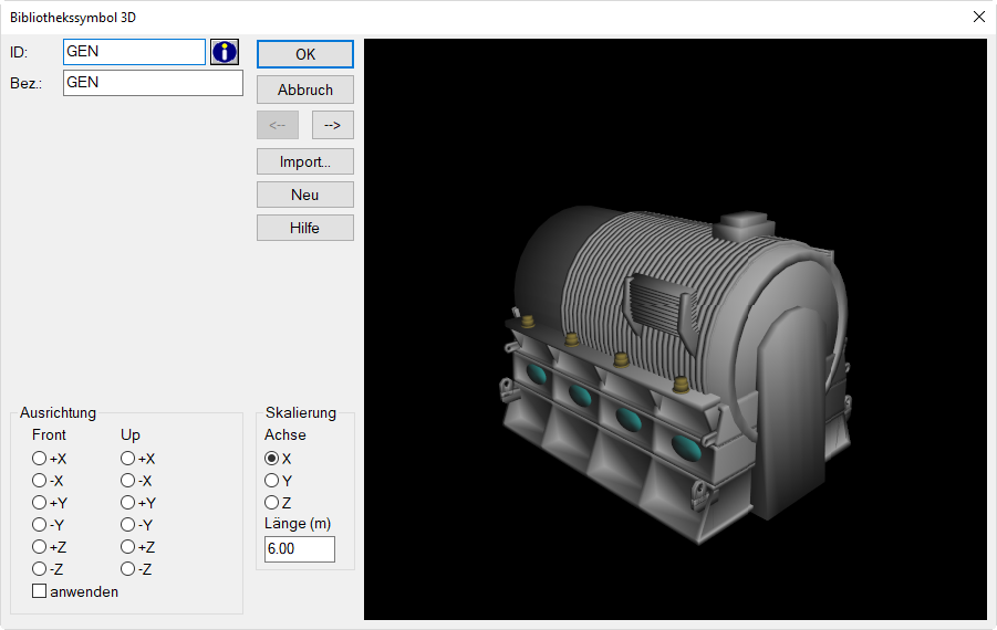
Object „Generator“, aligned and scaled in the 3D symbol library
Assigning the 3D symbol
This 3D symbol shall be placed at the location of an existing point source (at 1.5 m height) and displayed in the 3D-Special view. Proceed as follows:
- Select the object Symbol from the toolbox and drag a frame on top of the existing point source (enter a point source first if required).
Note
The size of the frame is irrelevant for 3D symbols since the symbol‘s size is determined by the value in the 3D symbol‘s library.
- Double-click on the border of the symbol‘s frame.
- Enter as the center coordinates of the symbol the coordinates of the point source.
- Select from the list box „3D-Symbol“ the option „Generator“.
- Make sure that the option „Align with ground“ is selected and that on dialog Geometry a relative height of 0 m is specified (default setting/ value).
- Close the Symbol dialog.
The 3D symbol is not displayed in the 2D view, but just the symbol‘s frame.
- Open the 3D-Special view using the key combination CTRL+3.
- Approach the 3D symbol navigating by the arrow keys forward/backward and the mouse.
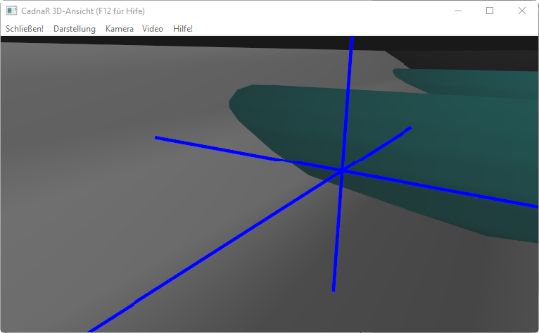
Drive/dive into the interior of the 3D symbol in order to locate the point source inside the generator‘s symbol (having a relative height of 1.5 m).